A Guide to 3D Printing Functional Gears

While the aesthetics of 3D printed objects is one of the strongest suits of 3D printing technology, it’s not impossible to make fully functional objects as well. You will have to be more exact with your settings to make reliable and functional prints, but you can make them even with simple filaments like PLA.
Gears are some of the most basic models you can print to be functional. For maximum learning, we suggest learning how to design them yourself. 3D printed gears are great for exercising your modeling and 3D printing skills for functional prints.
A few key concepts to understand
Before jumping headfirst into the process of designing gears, let us first discuss some relevant concepts. Gears make great toys because they look simple, but are really fun to play with. A gear assembly is also an excellent way to learn a few essential concepts in physics.
There are two parameters in designing any single gear – its pitch and the number of teeth. The ‘number of teeth’ is self-explanatory. The pitch of a gear refers to the number of teeth of a gear with a 1-inch diameter. A gear can have an odd number of teeth such as 11 or 21. It is far more important that the teeth of a gear fit perfectly with that of the other gears in the assembly.
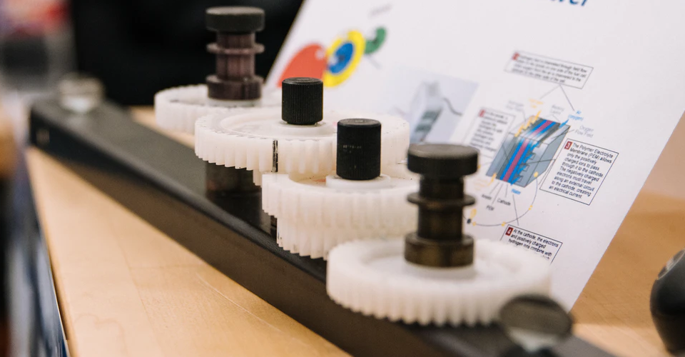
You are probably familiar with the appearance of a gear assembly made up of gears of different sizes. A gear assembly allows for the rotational motion in one gear to be transmitted across the assembly and produce motion on other gears. In some cases, the assembly can create rotation along another axis or even translate to linear motion.
A principal concept in gears is the conservation of angular momentum. This is a product of both the radius of the gear and the speed by which it is rotating. This momentum is transferred almost perfectly from one gear to the next, barring any losses because of friction. Thus, a large gear rotating at low speed can cause a smaller gear to rotate much more rapidly.
The more common scenario in gear assemblies is that the input force rotates a small gear rapidly. This is translated to a larger gear that rotates slowly but still has greater torque. This mechanism allows gear assemblies to rotate large objects or lift heavy objects with just a small application of force.
This translation of force can be estimated using the gear ratio of any particular pair of gears. This is a ratio comparing the number of teeth of two gears. For instance, a 6-tooth gear turning a 30-tooth gear yields a gear ratio of 5.
As we shall see later on, these parameters will play roles in the design of a gear for 3D printing.
Design tips for 3D printed gears
Nylon is the best material
While nothing is stopping you from 3D printing your gears in PLA or ABS, we find that Nylon produces the best results. Nylon is tough and is just flexible enough to withstand wear and tear but still provides good force transfer. It also has a high melting point to withstand deformation from heating because of friction.
A unique trait of Nylon is that it has a fairly low coefficient of friction. This is important in plastic gears where finding a compatible lubricant can be quite difficult. If you have to use a lubricant, we suggest using a silicone-based one.
PETG may be hailed as one of the best 3D printing materials, but we do not recommend it for gears. PETG is more flexible than either ABS or PLA. This is not a characteristic that we are looking for in this scenario. Flexible materials create poor force transfer, making a gear assembly much less efficient.
Bigger is better
If you have been printing in FDM, then you probably already know the pain of 3D printing very small parts. At the onset, it’s a good idea to be realistic about what your 3D printer can achieve. Do not design gears with pitch values of less than an inch, lest you end up with hard-to-control errors.
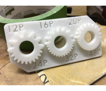
This advice is also valid for the design of gear teeth. Designing your gear with more teeth provides smoother rotary motion but will also require that you 3D print smaller teeth. Not all 3D printers may be equipped for this. This free model should help you determine the minimum size of gear teeth that your printer can handle.
Setting limits on the number of gear teeth
When designing a gear, you need to determine the maximum and minimum number of teeth that your 3D printer can handle. This test model will help you check your 3D printer’s capabilities from pitch values of 12 up to 48.
Reducing the number of teeth and using bigger teeth on your gears seems like a simple solution. Bigger teeth are stronger and easier to print. However, they also produce poor torque transfer. If you need your gear assembly to be efficient, you will have to strike a good balance between pitch and gear teeth size.
Set a maximum gear ratio of 1:4
A good way to set a limit on the size of your gears is to impose a maximum gear ratio of 1 is to 4. If you need your assembly to have a higher gear ratio, then we suggest breaking them apart into several smaller gears.
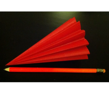
Triangular teeth or involute teeth?
The simplest shape for gear teeth is a triangle. As long as you use triangles with identical sizes, you should have no problem matching up pairs of gears. However, triangles have low efficiency in terms of torque transfer and tend to be quite noisy.
The most common gear shape is that of the involute circle. Involute gears are a little harder to design but are considered very efficient. This exceptional efficiency is made possible by the design of the involute gear that aims to have only a single point of contact between gears as they turn alongside each other.
Print with a solid infill
Gears can go through a lot of mechanical stress during operation. This does not bode well for 3D-printed gears, as they are not exactly well-known for their durability. The best you can do is to delay the inevitable onset of wear and tear by printing your gears as solidly as possible.
Enabling 100% infill gives your gears a bit of extra strength. Having more material in the internal space also reduces deformation, resulting in better torque transfer.
Don’t make your teeth perfectly divisible
It may seem intuitive to design gear pairs to have a number of teeth that are multiples of each other. For example, a gear with 12 teeth can pair up with another gear with 24 teeth, creating a perfect 1:2 ratio.
However, it’s considered good design to use 25 teeth instead. 25 may not be perfectly divisible by 12, but this also means that the same set of teeth will not meet up with each other for every revolution. This small design change slows down wear and tear on the gear teeth substantially.
Expect some post-processing
FDM printing is not exactly known for perfectly smooth surfaces so you will likely need to do a bit of post-processing on your 3D printed gears. Among the tasks are smoothing the gear teeth or boring center holes to make them fit your assembly. Keep in mind that you need these gears to fit perfectly snug with each other both for efficient load transfer and to avoid accelerated wear and tear.
The great thing about a 3D printed gear assembly is that you can just print replacement gears as necessary. Unlike metal parts, 3D-printed gears are cheap enough for you to not feel bad if they don’t turn out perfect.
Final thoughts
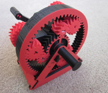
Gears can make for a very interesting project for your 3D printer. Seemingly simple, gears benefit greatly from high-precision 3D printing. If you want to sharpen your skills even further, then we recommend learning how to model and design gears from scratch.
If you don’t quite know where to start, then you can try 3D printing pre-made models such as these two simple gear assemblies. Pay attention to the shape of the gear teeth and how torque transfer works. With some practice, you can eventually come up with gear assembly designs that are far more complex.