How to Design Interlocking Parts for 3D Printing

Despite the fact that 3D printing is one of the most versatile additive manufacturing technologies available today, it still has several limitations. Yes, you can create just about anything on a 3D printer – given that it fits on a build platform and that your 3D printer can handle your filament material.
The good news is that there are a couple of ways that you can work around these limitations. Among experienced users of 3D printers, a favorite practice is to break down a model into separate interlocking parts. What’s the point of going through this complexity? Are there any best practices to ensure that your interlocking parts fit securely and snugly?
Why make a design with interlocking parts?
To be honest, breaking down your model into separate, smaller parts and designing interlocking joints for each of them does make your design a bit more complex. It also takes longer to print and uses up more filament. What’s the point of going through this compromise, anyway?
1. Print large objects
The most common reason for why 3D printing professionals break down their models into interconnected parts is if they intend to print a design that is way too big to be printed all at once. While it’s also possible to simply slice your models into smaller pieces and glue them back together once you’re finished printing, having interlocking parts gives your multi-part assembly a much higher level of durability.
2. Print with minimal supports
Support structures are par for the course when it comes to 3D printing, but there’s no doubt that they are a huge waste of filament. If this isn’t an issue, then you can go right on ahead and print your model as is. However, there might be a way for you to minimize the amount of filament that goes into support structures by splitting the model into smaller parts.
3. Make prints with several materials or colors
Some high-end printers come with a dual extruder system, allowing you to print objects made with two different filaments. If this is a luxury you don’t have, then it’s perfectly fine to split your model into different parts so that you can use different filament materials. The beauty of this method is that there’s no restriction to the number of different filaments that you can use – you can go crazy and use ten different filaments!
Once you get into the mindset that it’s always possible to split the model you’re working with into different parts, you can open up a whole world of options for your 3D printing project. The upgrade in design freedom is amazing, and you’ll never go back to that single-piece mindset.
Types of interlocking connections
The tough part of modifying models to have interlocking parts is that there’s no one-button function in 3D design software for it. Instead, you’ll have to pick a point where you want to split your model and add in the necessary modifications yourself. However, it’s not all that hard. With a little practice, you will be able to add interlocking connections on your models in a few minutes.
The following are some of the most commonly used methods to create an interlocking connection. The best method may vary according to the geometry of your model or the intended use of your 3D printed object.
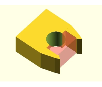
1. Pin and cavity
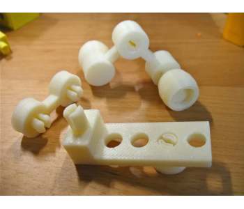
The simplest interlocking connection, this method simply creates a thin cylinder on one half of the connection, and a similarly-sized cavity on the other. The specifics of the process may vary between different software platforms, but the basic principle is the same: make a split in your design, add a cylinder to one half, add a Boolean modifier to the same cylinder and apply it to the other half.
When doing this method to create interlocking joints, always keep in mind to respect the tolerance of your printer. We’ll get into more detail on this later, but the tolerance is basically a measure of how accurate the objects coming out of your 3D printer will be with respect to the measurements you’ve set on the slicer software. What this means is that you cannot expect a round peg to fit perfectly into a round hole of exactly the same size. Instead, you’ll need to expand the hole just enough to make the peg fit snugly.
It’s also worth noting that using a cylindrical connector allows the adjoining parts to rotate around the joint. Depending on your design, this may or may not be a desirable feature. If you’d like the parts of your model to be rigid once they are joined together, then you may build a connection using a square peg.
Another thing you’ll notice about a pin and cavity connection is that the parts are easy to separate as they are to join. If you want a connection that is more permanent, you will have to apply an adhesive to the overlapping connection. However, if you want a connection that stays put without being permanent, then a snap-fit connection may be what you are looking for.
2. Dovetail
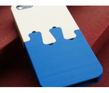
A dovetail connection is a type of interlocking connection that is very stable yet easily removable. Taking its name from the shape of the connectors, a dovetail connection is similar to what you would find in jigsaw puzzles. They aren’t exactly the most versatile since they are best used on flat and thin objects.
A dovetail connection provides a lot of contact between the two parts that it is joining. The resulting increase in friction makes dovetail connections very hard to break. In fact, dovetail connections are virtually impossible to separate by tension forces. The increased contact area is also great for applying adhesives.
3. Cantilever snap-fits
Snap-fit connections are nothing new. In fact, you probably encounter them several times a day. As its name implies, a snap-fit connection contains a part that “snaps” into place to create a firm but temporary connection. Since they are virtually everywhere, assembly and disassembly of snap-fit joints have become intuitive for most people.
The most common snap-fit joint is the cantilever – a narrow beam with a protrusion at the end, such as a hook or a bead. The protruding end is inserted into a cut-out slot on the other half of the connection. Once the protrusion has been fully inserted, it snaps back into place and locks the two halves of the connection in place.
A bit more thought is needed when designing a cantilever snap-fit joint. The parts connecting a snap-fit joint go through an exceptional amount of stress during insertion, so they must be designed with durability and even stress distribution in mind. The worst that could happen is that your cantilever joints can snap off because of the excessive stress. There are a couple of best practices that can be done to achieve this.
A good piece of advice is to build snap-fit joints horizontally. As you may well know, FDM printing is anisotropic in nature. This means that the points and the axis at which the layers bond with each other are much weaker compared to any other direction. By building your joints horizontally, the weak points of the joints are spared from the highest levels of stress during insertion.
Another easy remedy is to “fillet” the base of the cantilever, or to give it a smooth and curved base. You can play around with the radius of the fillet, but whichever settings you pick should still result in better stress distribution.
4. Annular snap-fits
Annular snap-fits are basically snap-fits with a circular cantilever. A common example are the caps of pens. Annular snap-fits do not need a narrow beam and are therefore less prone to mechanical damage. As you can tell with the usual pens, this type of snap-fit connection does not easily get worn out even with long-term and frequent assembly and disassembly.
Aside from the superior mechanical strength of annular snap-fits, they can also be designed to fit so snug that they effectively become water-tight. Most of the same design principles that are recommended for cantilever snap-fits also apply to annular snap-fits, such as having fillets and setting a build direction that reduces stress along the weak points. Snap-fits are best made using a filament material that is both strong and flexible, such as nylon.
How to determine the tolerance of your 3D printer
We’ve already mentioned the concept of “tolerance” above, which determines how well interlocking parts will fit into each other. Common sense dictates that the cavity of any interlocking connection must be slightly bigger than the solid “plug.” The question is: by how much?
Different sources recommend different values for the tolerance of an FDM printer. Some might say that 0.5 millimeter is a good rule of thumb, while some claim to be able to go as allow as 0.2 millimeter for snap-fit joints. With these conflicting claims, which one should you follow?
Our advice – none of them. The tolerance of your printer depends a lot on your printer’s unique calibration settings. Different filament materials may also react differently during cooling, resulting in different tolerance values.
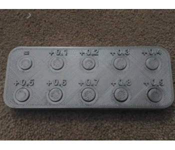
For best results, we recommend determining the tolerance values for your specific printer and filament combination by printing a simple tolerance test model such as this one from Thingiverse. The model is basically a series of buttons with different gaps (from 0 to 0.9 millimeters), and you’ll just have to check which clearance value provides a fit that is just snug enough.
Final thoughts
Modifying models to have interlocking parts is something that only more advanced 3D printing professionals would resort to. It’s a great little way of spicing up an old model, scaling them up and breaking them down into more manageable pieces. It also paves the way for the possibility of building a model out of different filament materials and colors
If this something you haven’t tried yet, we certainly recommend giving it a shot, even if just for fun. Designing interlocking parts and testing out how well they fit each other provides a lot of insight into how accurate (or inaccurate) your printer is. More complicated interlocking connections, such as snap-fits, also take a lot of practice to perfect. Why don’t you get those mistakes in now so that you’ll perfect the craft in the future?