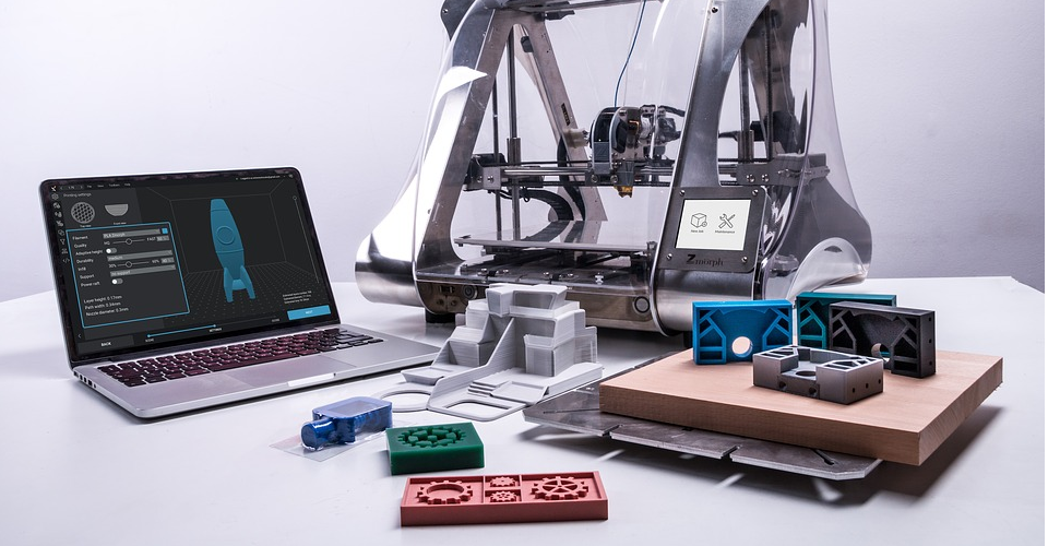
How to Design Parts for 3D Printing

3D printing is an additive type of manufacturing process. It involves adding a new layer of material over the previous layer to make the final part. This is very different from the traditional subtractive manufacturing process of starting with a block of material and then carving/machining away bits of that material to get the end product.
3D printing also has different processes for manufacturing such as SLA, FDM, SLS, and so on. While there are subtle variations in the best practices for each type of 3D printing process, certain guidelines are applicable to and common across all 3D printing processes.
The following are some key considerations which you are encouraged to take into account in order during the design phase so as to get the best quality of print at the end:
Digital Freedom vs Physical Realities
Every 3D part is first designed in a 3D modeling software. This software is digital and in the digital world, you can design pretty much anything. While it is great to be able to achieve complex designs in the digital software that may, at times, defy the laws of physics and gravity, the real world is very different from the digital world.
Ultimately, the part you design will get printed and it has to be in sync with the physical world limitations. So, always keep in mind that just because a design is achievable in a software program, that does not necessarily mean that it will all work out in the physical world. Think of gravity and physics too.
Orientation
The orientation of your model impacts the end result in a highly significant way. If you get the orientation wrong, then you risk making the 3D printing process more complicated, expensive, and time-consuming. Hence, orientation is something you need to consider when you design your model in the software.
You need to orient your model in a way which minimizes or removes the need for the use of supports. The orientation should also be such that you can print overhangs that are at a smaller angle than 90 degrees. An even better option is to orient your model in a way such that the overhangs are actually vertical and pointing up towards the ceiling with a flat surface below them.
If any sections of your model have high levels of detail, then you could consider having those sections along the Z-axis which is a much finer resolution than the X and Y axes. While thinking about orientation, think about what 3D printer you will use and what its strengths are. Orient your model accordingly to align with the functionality of the printer to get a part that is accurate and strong.
Single piece vs splits
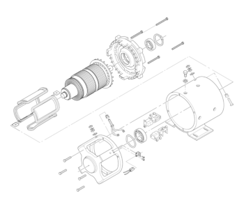
Sometimes, it may be better to split a single large part into multiple pieces that are smaller and simpler. It may be more time and cost efficient to print these smaller individual portions and then fit everything together at the end. Often times, a single large part is more complicated, tends to require more support, overhangs, post-processing, and more steps to print.
Take for example any rotating part like an impeller or a wheel assembly. Such parts consist of an axle and a circular section. Printing the whole thing at once will be quite complicated. But splitting such a design into two smaller designs is a better option. You can print the axle and then the circular portion. You won’t require any supports and overhangs either.
If your 3D printer can accommodate two models at once, then you may be able to print both the axle and the circular portion simultaneously. So, you get the same part as the larger complex one in the same amount of time as if you were to print the larger part as one piece. However, the amount of complexity and post-processing required goes down significantly (or even completely in many cases).
Always think about the complexity when you begin designing and whether it is worth splitting the part design into smaller more manageable sections.
Keep an eye on tolerances
When you print multiple components of a larger part or assembly, then it is absolutely critical that every single component fits with its counterpart after all the printing has been done. After all, if the parts don’t fit, then the assembly isn’t of much use. And to make matters even trickier, you don’t find out about the issue of non-fitting parts until after the printing process. To then go back and try to fix such problems can cost money and take up valuable time by means of significant post-processing.
So, when you design individual components of a larger assembly, keep the tolerance levels in mind. After all, tolerance mismatches can ever so slightly throw off the sizes which can cause the problems outlined above. There are two main types of fitting mechanisms most commonly used. The first is a slide fit and the second is a press fit. Press fit requires high levels of tolerance, with a recommended reference level of 0.2mm. Slide fit is relatively more flexible, with a recommended reference level of 0.4mm.
Certain parts like gears will demand much higher tolerance levels. The 3D printer itself will have slight inaccuracies that should be factored in when designing a part.
Wall Thickness
Wall thickness needs to be given special attention. Every 3D printer will have a minimum wall thickness but it is a good idea to design your 3D parts such that the minimum wall thickness across any section is at least 1 mm. If you are designing vertical wires, then the length to width ratio should be kept to a minimum. The smaller this ratio, the better will be the quality of the printed part.
Overhangs
Overhangs are sections that stick out and hang with only partial support or often times absolutely no support below them. They essentially are keeping themselves up against gravity. Since 3D printing is an additive “layer-by-layer” process, it is not possible to print something like an overhang in thin air. Generally, every layer that a 3D printer prints rests on some underlying material. So, 3D printing overhangs can get quite complicated.
One recommendation, therefore, is to minimize or completely avoid overhangs if possible. That way, you do not have to worry about them or their effects on the quality of the model and the finish. If you cannot escape the use of an overhang, then you will have to use a support below the overhang. While this solution may sound quite simple, the problem with using supports is that removing the support after printing can take a lot of time and leave rough marks on the surface of the model.
You can also try to design the model in such a way that the surface goes gradually beyond the corner rather than in a perfect right angle. You can also try and print the edge surface at an angle. Most 3D printers allow up to 45 degrees of angle when printing.
Chamfers and Fillets
Thin parts, when 3D printed, tend to be weak and brittle. In fact, they could break even during the actual printing of the part. So, when you design such sections, make sure you add fillets at the base of such thin sections. Fillets are curves that are designed at the interface or connection point of two straight surfaces. These fillets will strengthen the base portion and add durability to the part.
You can also think of designing chamfers along the edges of a cube or a straight surface. Chamfers remove the need for having right angles which increase the risk of warping and other imperfections. The stress on the model during the printing process is also reduced through the use of chamfers.
Holes
When making holes in your parts, note that the 3D printer does not print your designed hole in a circular shape. Rather, the circle of your hole is shaped as a polygon. The vertices of this polygon touch the circumference of your designed hole’s circle. So, the diameter of this 3D printed hole will not be exactly as big as you may desire.
The solution to this problem is to design your hole with a diameter slightly larger than what you calculated. You are advised to take into account a buffer of 0.2mm and then add some more for tolerance level of the 3D printer.
Use Dowels if using Pegs
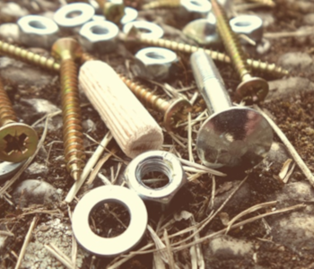
3D printed parts which have holes and pegs and which need to be fitted together by slide fitting or push fitting can sometimes break. The reason for snapping is the fact that there is high pressure exerted on the peg or the area which interfaces with another part.
To avoid this, the natural reaction would be to somehow reinforce the peg or the area which will come into contact with the other part being fitted. Reinforcing is done by using more material or adding extra layers of material. But, you can avoid the extra material cost and time by using dowels. Compensate for the higher pressure and increase the strength of the interfacing portion of your 3D printed part by using a dowel.
Detailing
Detailing looks great on the end product. But, when you design the detailing on your part, keep in mind the capability of the 3D printer that you plan to use. Each printer has a minimum feature size that it can print. You also need to think about the layer height that the printer can give you. If your printer cannot handle the kind of intricacy that you want, then design a part with a lower level of intricacy and detailing.
This advice goes back the first point of this article i.e. the digital world and the real world have to be in sync with each other.
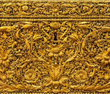
Embossing and Engraving

Embossing is a process where certain specific portions of a surface are slightly raised to display logos or letters on the surface. Engraving is the incision of a design, pattern, logo, or letter into a flat surface by cutting into the surface. 3D printers perform both embossing and engraving, but up to a certain limit.
Various 3D printing processes have different limitations on performing embossing and engraving. For an SLA printer, the minimum embossing requirement level is 0.1 mm. For the FFF process, it is much higher at 0.5 mm. Similarly, for engraving, SLA printer will require 0.4 mm while an FFF printer will require 0.5 mm. This has to be factored in when designing the embossing and engraving over the surface of the part being created.
So, no matter what software you use or what kind of part you create, you must always keep in mind the above guidelines when designing. Following them will save you a significant amount of cost and time. The key is to know your 3D printer and its specifications so that you know its minimum and maximum levels of details and other parameters. Design for the application and also for the printing process that you plan to use. And always design with practical limitations in mind.