Autodesk Inventor Starters Guide – Making a 3D Printable Spinning Top

Introduction
Autodesk Inventor offers a set of tools for creating 3D mechanical designs, simulations and documentation. The program gives users the ability to digitally prototype and validates their designs before any manufacturing needs to be done, reducing cost and time wastage. Inventor is an important tool for engineers wanting to design and develop new or even existing products/projects.
This user guide will cover the basics of Autodesk Inventor, just scratching the surface of what this 3D modelling program is capable of. You will be taken through making a project file and then modelling a simple part. Tools such as the sketch and extrude commands will be used to develop a part that is ready to be 3D printed.
Autodesk Inventor Professional 2015 will be used for this user guide. A free student version is available through the following link – http://www.autodesk.com/education/free-software/all.
Chapter 1 – Starting and making a project file
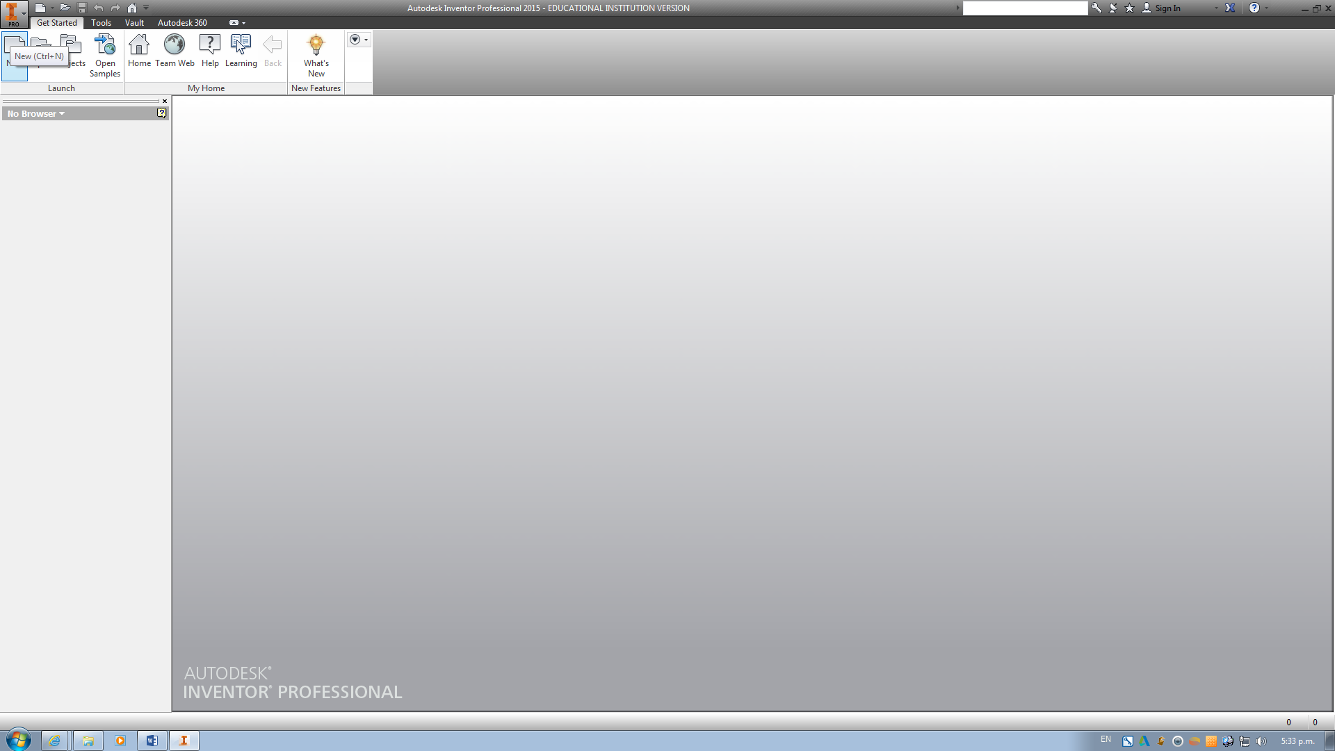
The first step is to make a project file. Project files are an integral part of Inventor because they hold all the files for a particular project or part. Once Inventor has opened you should be greeted by a screen similar to the one below. If not, a screen similar to Figure 2 or 3 should appear when Inventor opens. Close the ‘Welcome to Inventor Home’ tab.
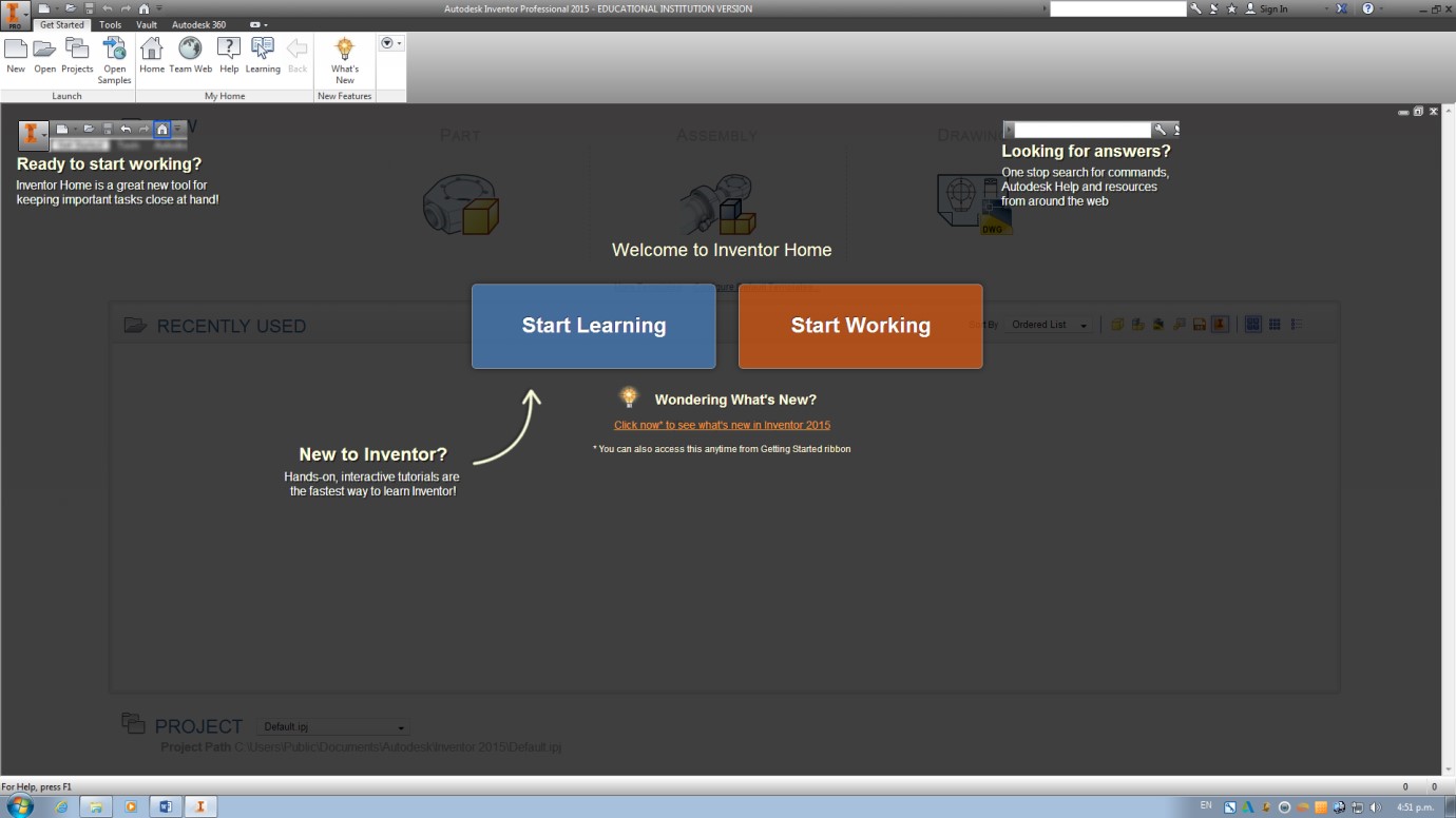
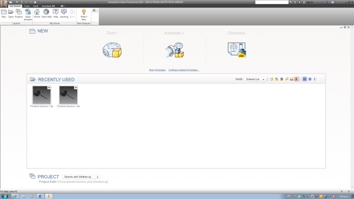
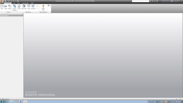
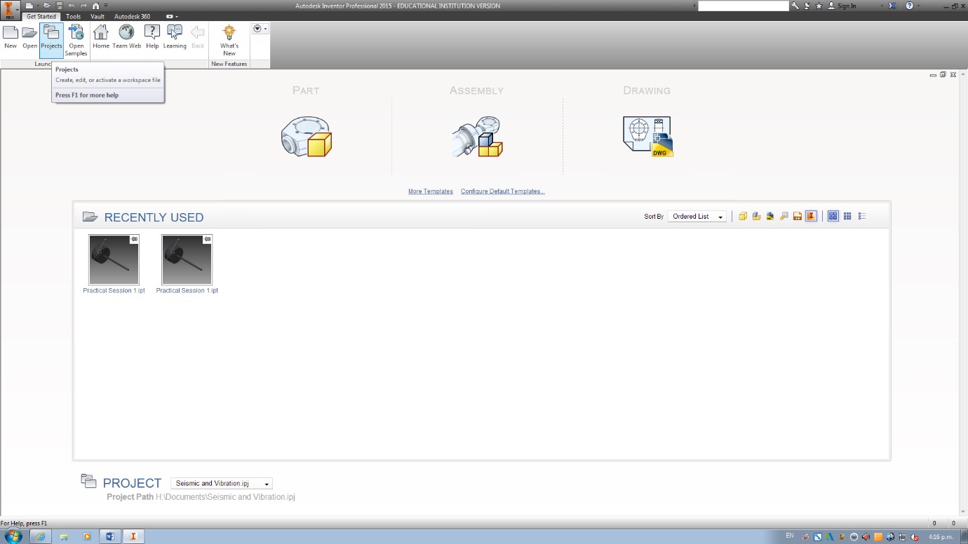
Now that Inventor has started, it is time to familiarise yourself with the different options available to you. The ‘I Pro’ at the top of the screen is where you can save, open, export and manage the part or parts you are operating on. Just underneath the ‘I Pro’ button is the ‘Ribbon’. Autodesk’s ribbon is where you can select what it is you want to do, whether that is making a new part, creating a sketch or making a project file, amongst many other things. The browser (seen in figure 4) is on the left of the screen and contains all the information from the part/parts that are currently being opened.Another tab showing recently used files may appear which is shown below in figure 3, or you may be greeted by a similar screen to figure 4. Do not worry about this as it does not change the next step.
Click on ‘Projects’ which is found on the ribbon.
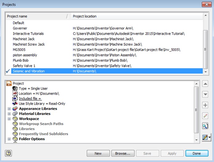
Under projects you will notice there are a few options. You will also notice there are a couple of projects already available to use; ‘Default’ and ‘Interactive Tutorial’. Default can be used if you want to quickly make up a part; however making all your parts in Default is not a good idea as it makes the project folder cluttered. Interactive Tutorials is for Autodesk’s own, in-house tutorials. We’re not going to worry about the text box below the top one for this tutorial. Go ahead and click on ‘New’.
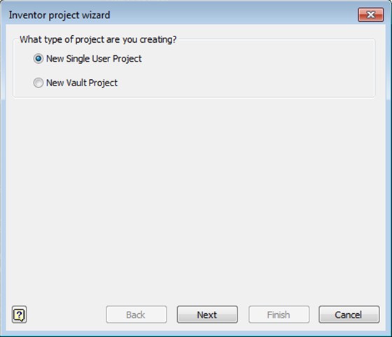
The ‘Inventor Project Wizard’ should appear. For this tutorial select ‘New Single User Project’ and click next.
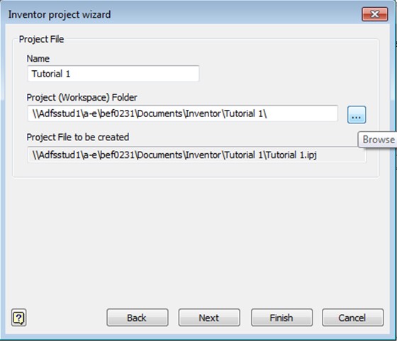
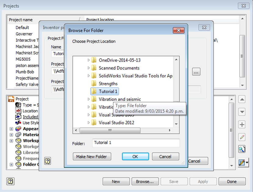
The following tab should appear. Under ‘Name’ type Tutorial 1 and then select where you want the file placed on the computer by clicking on the button on the right of ‘Project (Workspace) Folder’. A folder called ‘Tutorial 1’ was previously created for this Tutorial.
Click ok.
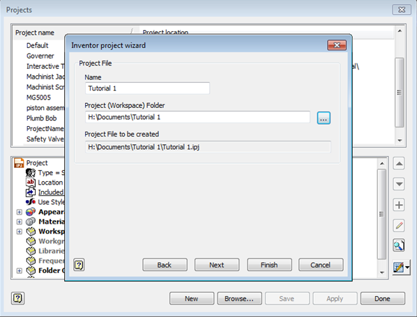
All part files and files related to this project will now be placed in the designated folder (Tutorial 1 in this case). Click finish.
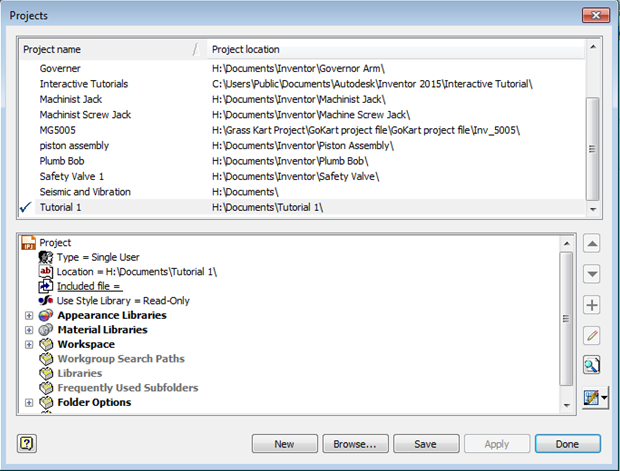
You will notice that the new Project file appears in the top box. The tick on the left hand side of the ‘project name’ shows that the project file is selected and all parts created will be placed in that file. Click save and then done.
Well done, you’ve created your first Autodesk Inventor project file. The next step is to model up a part.
Chapter 2 – Making a Sketch
In this chapter we are going to sketch a simple part. A number of commands will be used and you will learn to fully constrain your sketch. To make a new part file click on ‘New’ under the ‘Get Started’ tab on the ribbon.
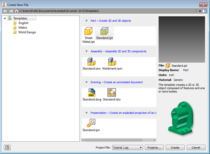
The ‘Create New File’ window will pop up. This is where all the drawing, assembly and other document types can be selected. You will notice at the bottom of the window next to ‘Project File’, ‘Tutorial 1’ is selected. You can quickly change which project file you want to work on through here; however for this tutorial we are going to keep using the file we created in Chapter 1 (Tutorial 1).
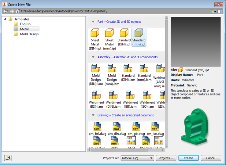
Click on Metric under templates, the following window should appear. Select ‘Standard (mm).ipt’ under ‘Part – Create 2D and 3D Objects’ and then click create. This means the part created will be in metric units (millimetres).
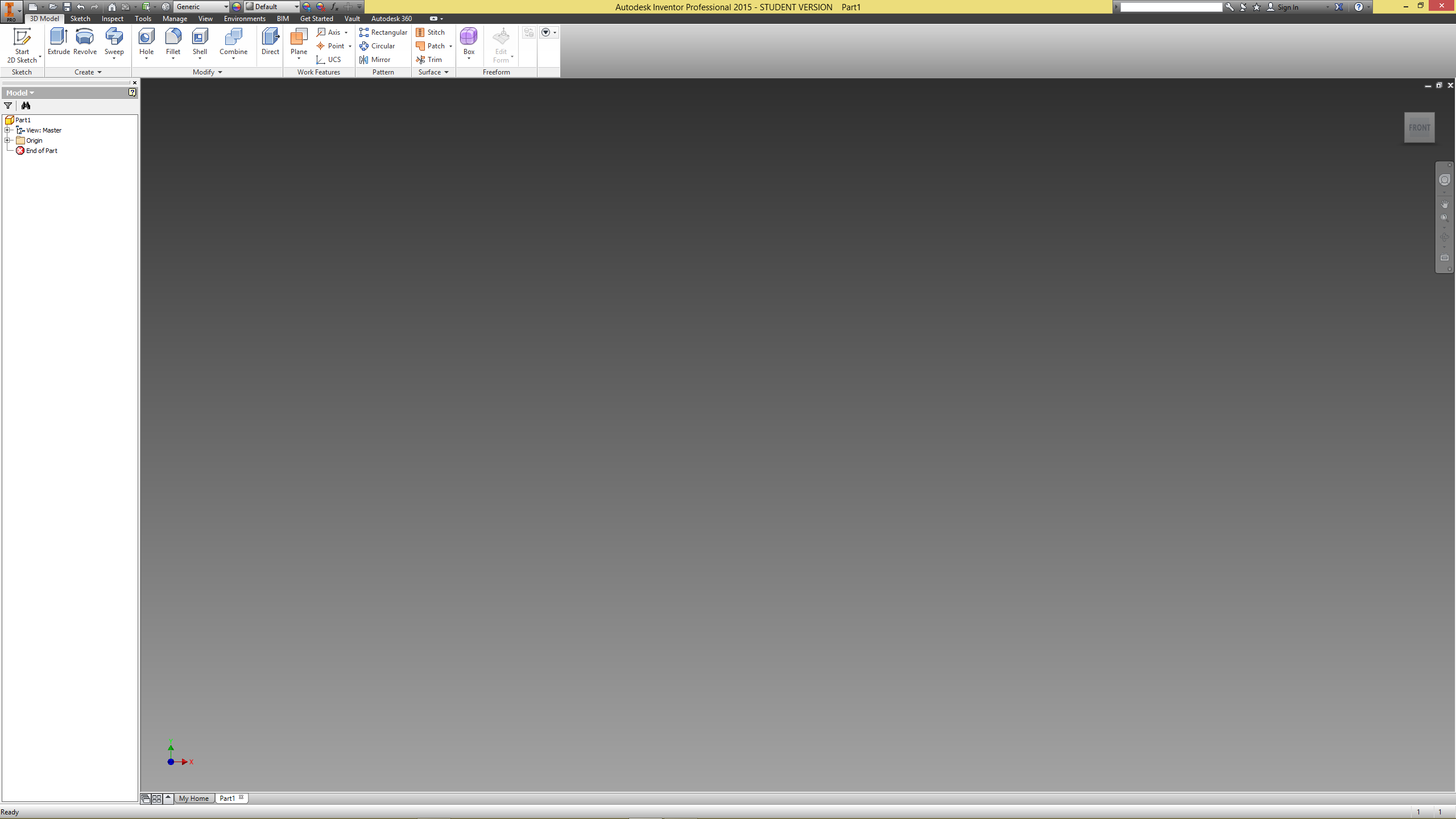
The next screen will appear. You will notice the ribbon has changed and the browser on the left of the screen has changed as well. On the top right of the screen a small cube is visible. The cube allows you to change viewing planes by selecting the arrows or the edge of the cube. Clicking and holding the cube pivots the view, which can also be done by holding down ‘f4’ on the keyboard.
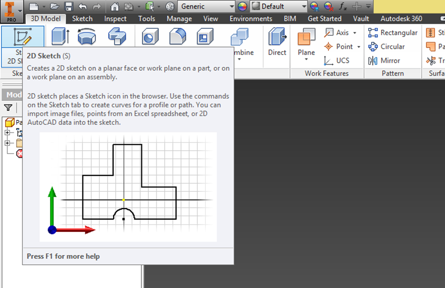
On the ribbon select the sketch command. Use the sketch command whenever you want to make a new sketch.
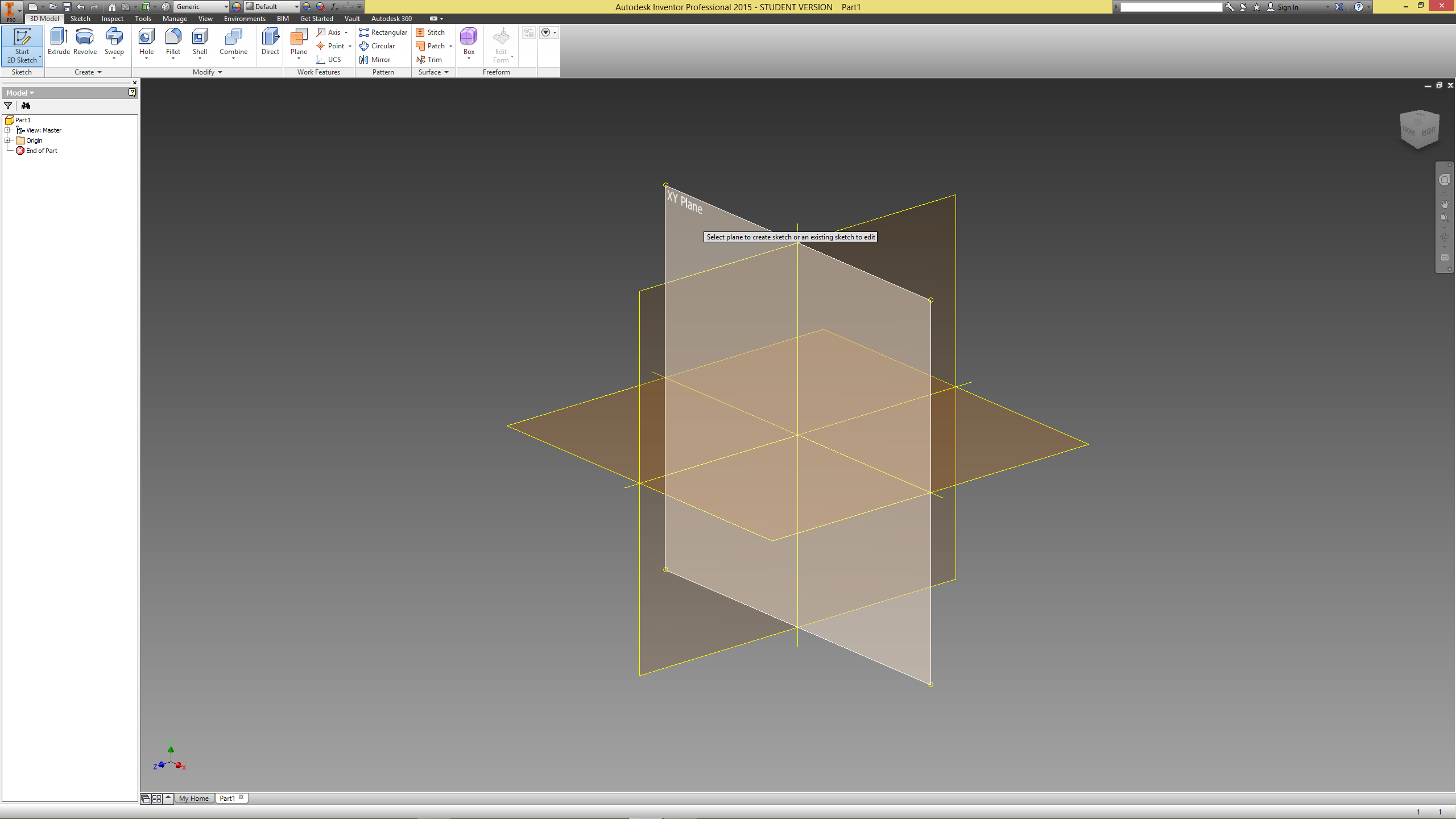
The following planes should appear on your screen. These are the YZ, XZ and XY planes which can be found by expanding ‘Origin’ in the Browser. For this tutorial the XY plane was selected.
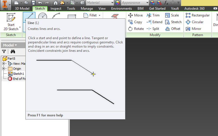
A new sketch will be started on the XY plane. Once again the ribbon has changed to accommodate the new sketch commands. Click on the line command.
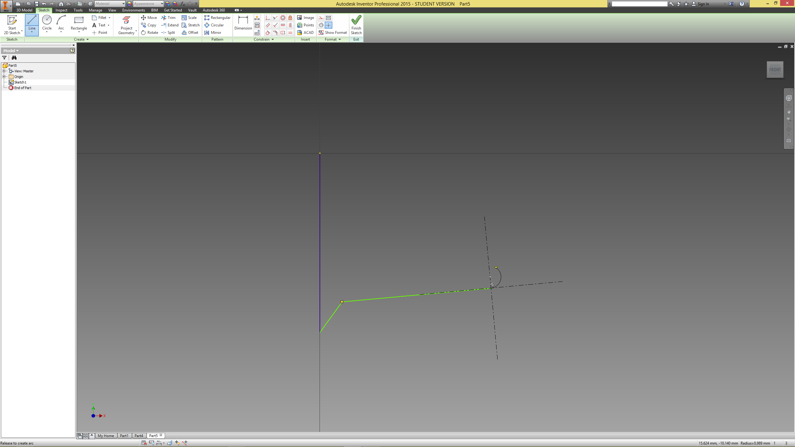
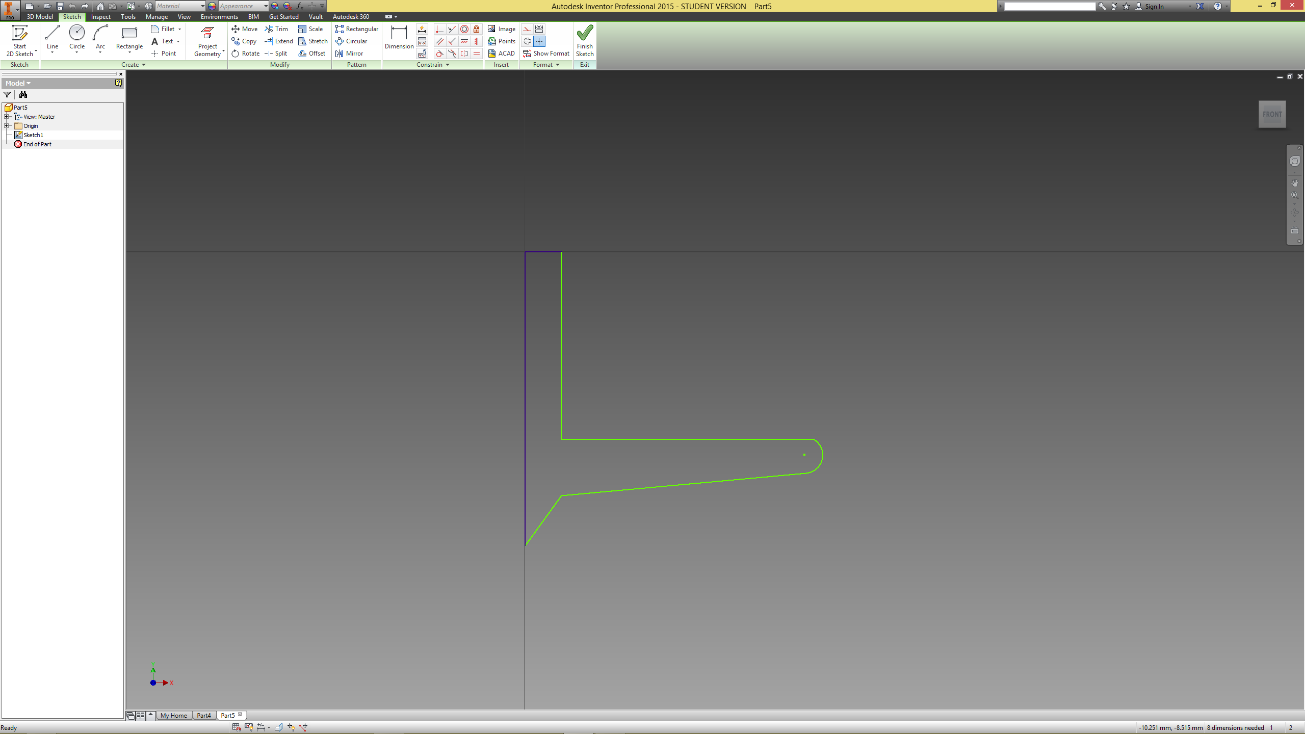
Start the line on the centre point and draw the shape below (note; it does not have to be exact at this point, we will add dimensions later). There are a number of ways to draw the arc. The first is to use the arc command, which can be found in the ribbon. Another method is to use the line command. Click once on the point where you want to start the arc and then click and hold on the same point to draw the arc (method used in this tutorial).
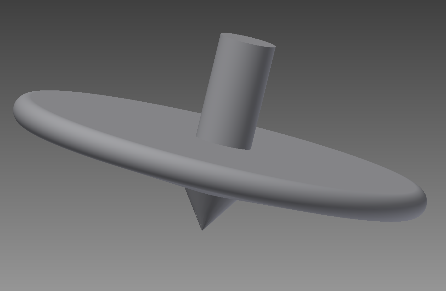
Continue drawing until you have a shape roughly similar to the one in the image below. You might have noticed that the shape resembles half a spinning top. This is because the ‘Revolve’ command will be used, although this comes later in the tutorial.
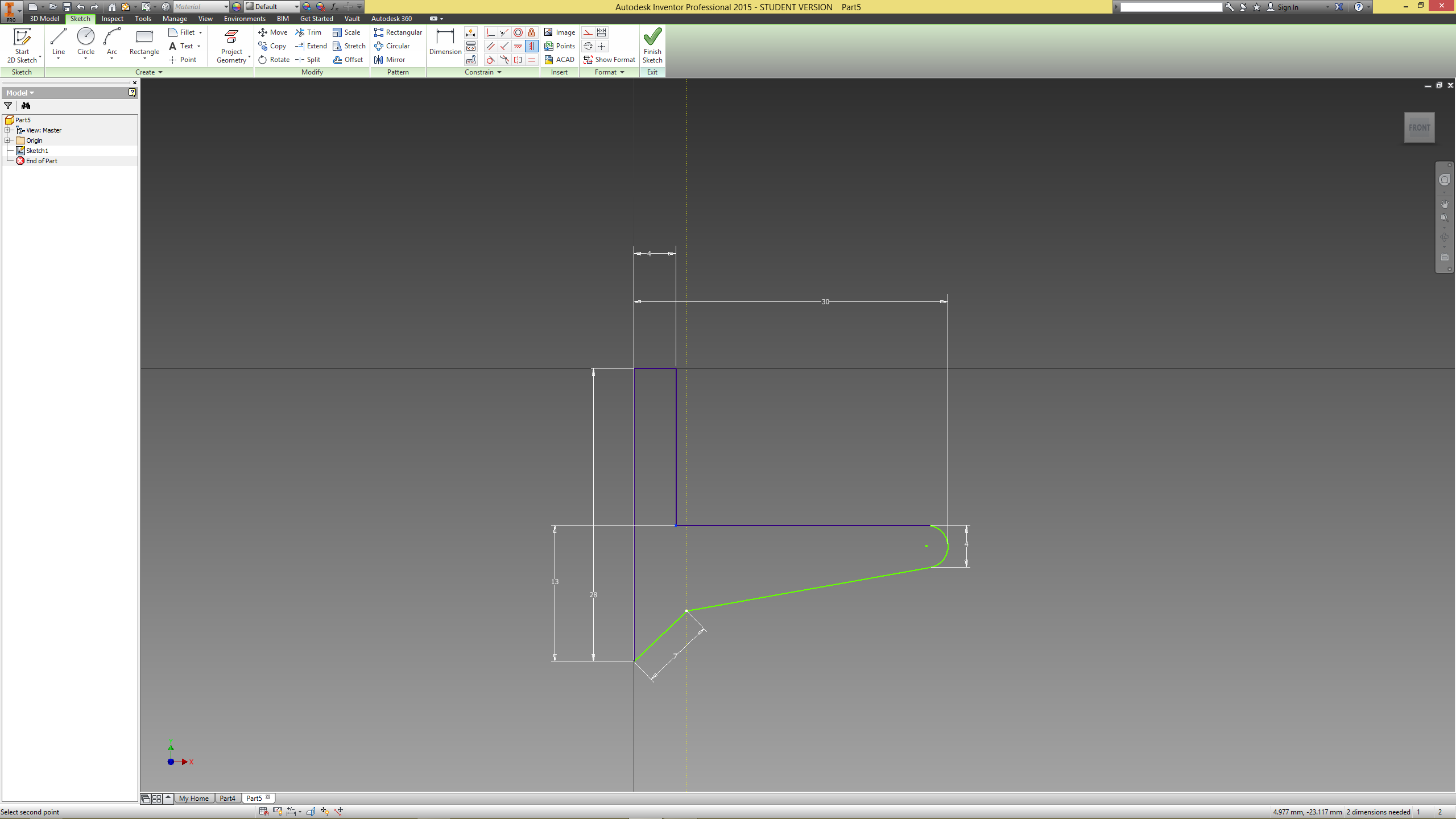
Now that we’ve got the rough shape of the spinning top, it is time to add some dimensions. At the bottom right of the screen you will notice that a number of dimensions are needed (eight in this case). You will also notice that some of your lines may be dark blue and some will be green. A fully constrained (dimensioned) sketch will have all blue lines. Go ahead and select the ‘Dimension’ command under ‘Constrain’ in the Ribbon.
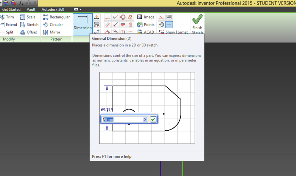
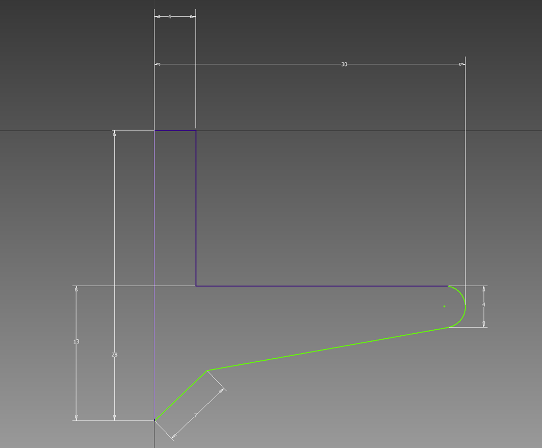
Dimension the sketch to the following. You will notice that two dimensions are still needed and a couple of green lines are still present. Sometimes the dimension command isn’t enough and some of the other constrain commands are needed.
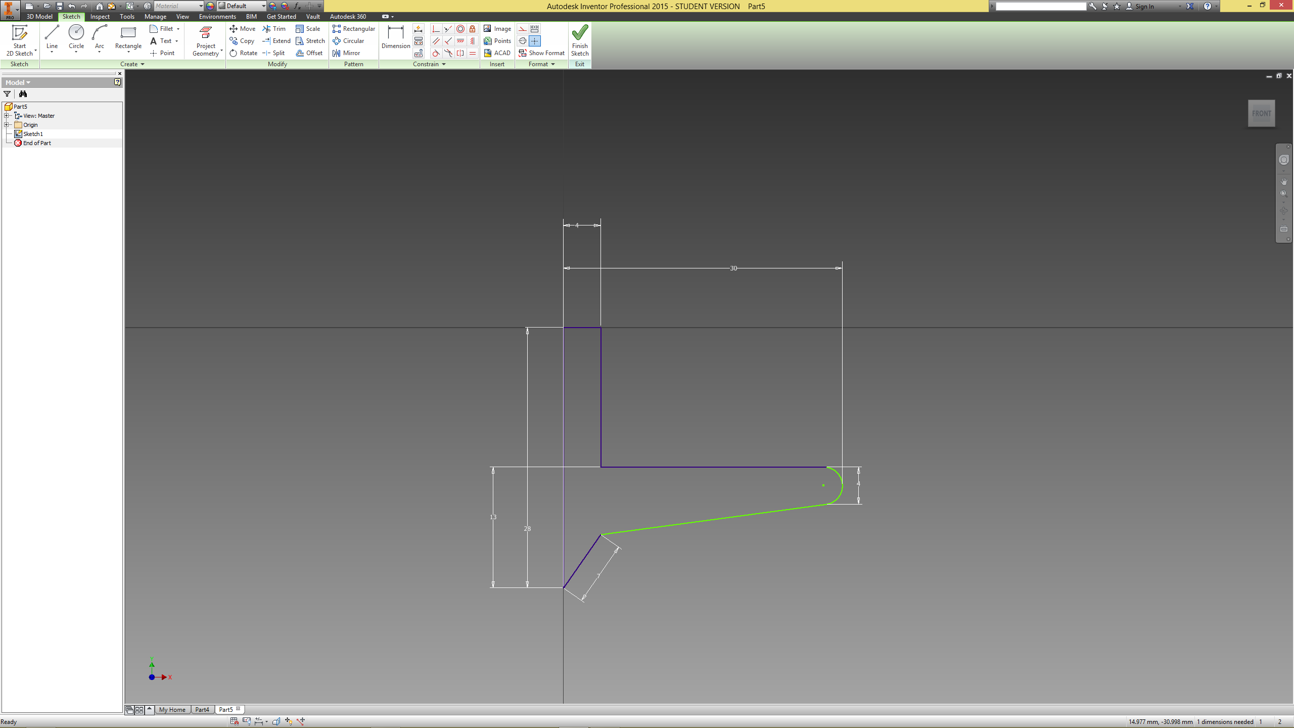
The first command we’re going to use is ‘Vertical Constraint’. Vertical constraint causes lines, ellipse axis or pairs of points to lie parallel to the Y axis of the sketch coordinate system. Select the two points that connect the main disc to the handle and point of the spinning top.
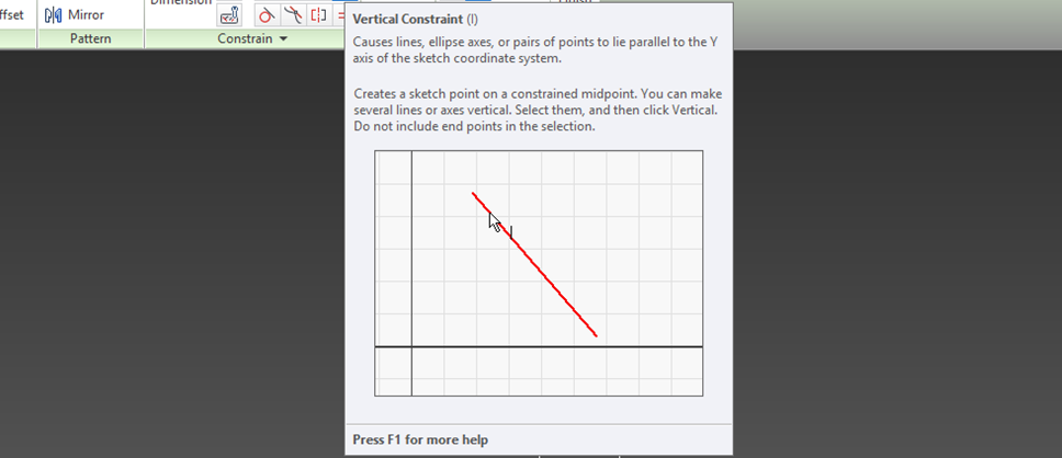
These points will now line up, removing one of the missing dimensions.
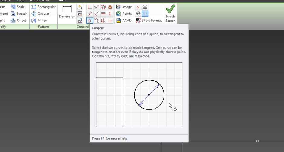
The second constraint command we’re going to use is the ‘Tangent’ constraint. This constrains curves, including ends of a spline, to be tangent to other curves or lines. Click on the arc and the top line of the main disc.
The sketch should now be fully constrained and no further dimensions or constraints will be needed.
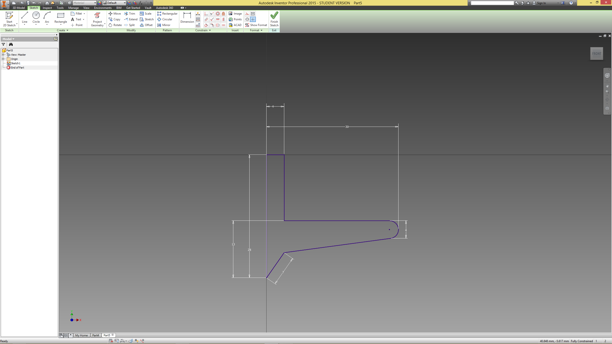
Finish the sketch by either clicking ‘Finish Sketch’ on the right hand side of the ribbon, or by right clicking and going ‘Finish Sketch’. You have now completed your first sketch; in the next Chapter will explain how to revolve the sketch to make a 3D model.
Chapter 3 – 3D Modelling
In this Chapter you will be shown how to turn a 2D sketch, into a 3D model. Saving and exporting the model will also be explained. From the previous chapter, you should have something similar to the sketch below.

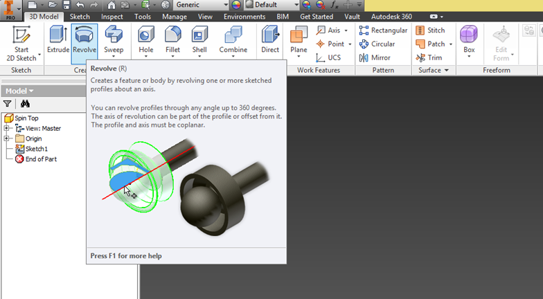
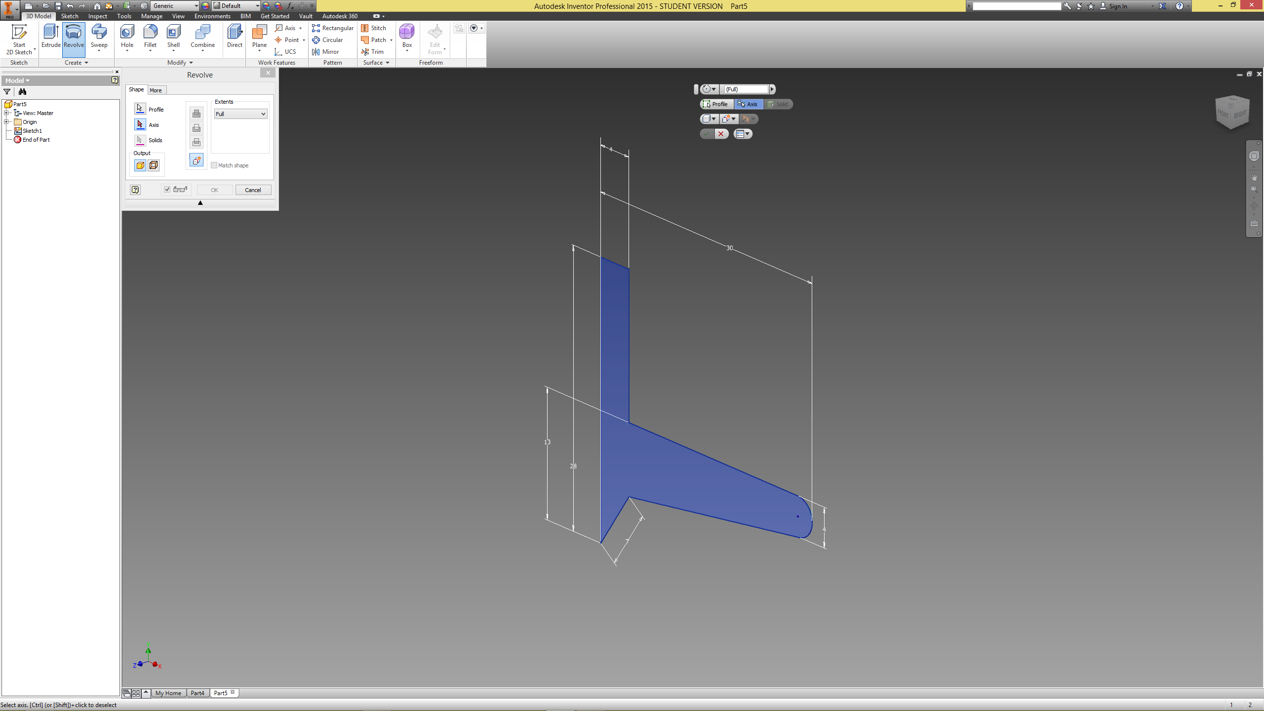
Along the ribbon, find the ‘Revolve’ command. Revolve creates a feature or body by revolving one or more sketched profiles about an axis. Select ‘Axis’ and click on the middle/centre line.
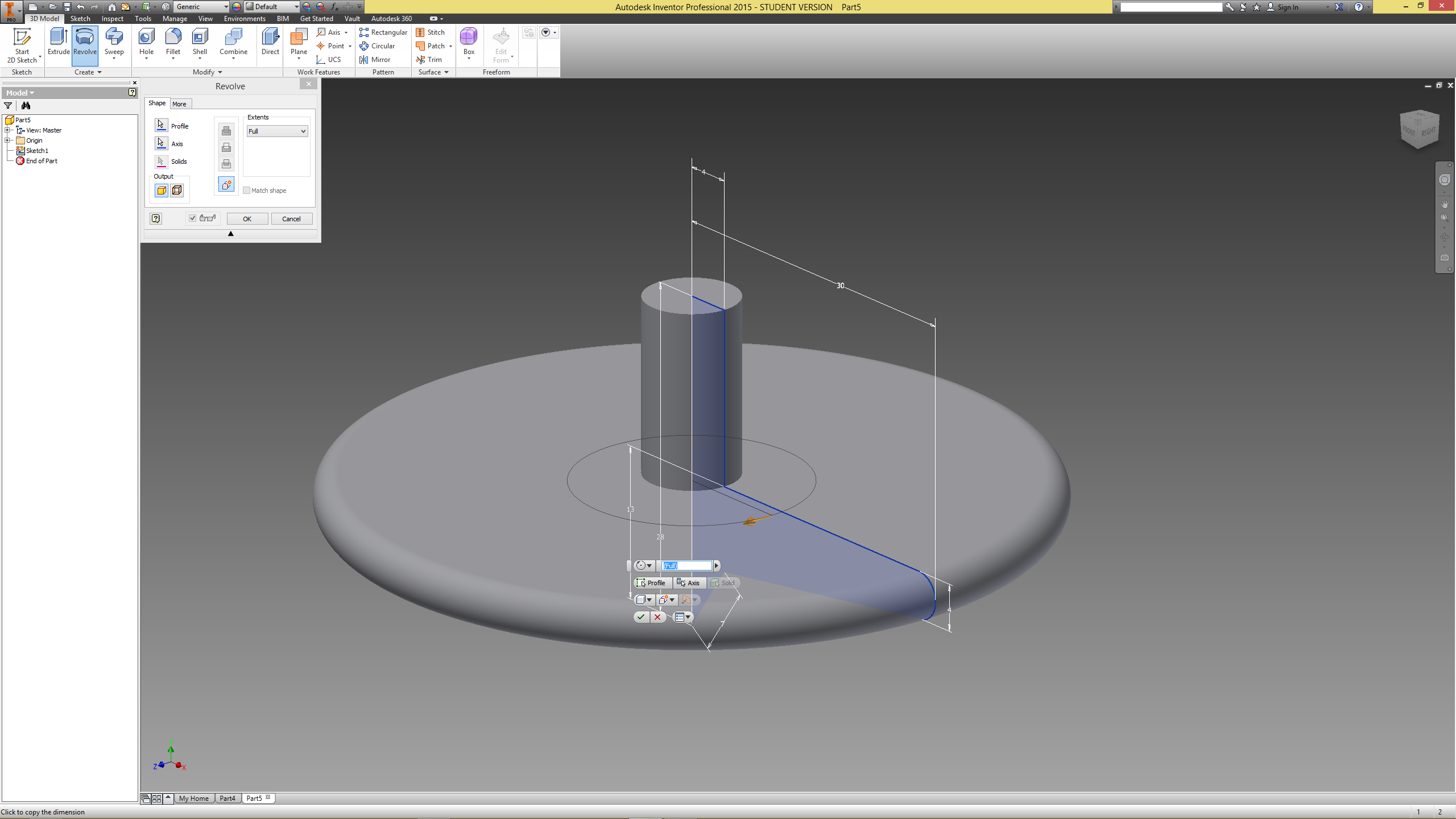
The following should appear. Click ‘ok’
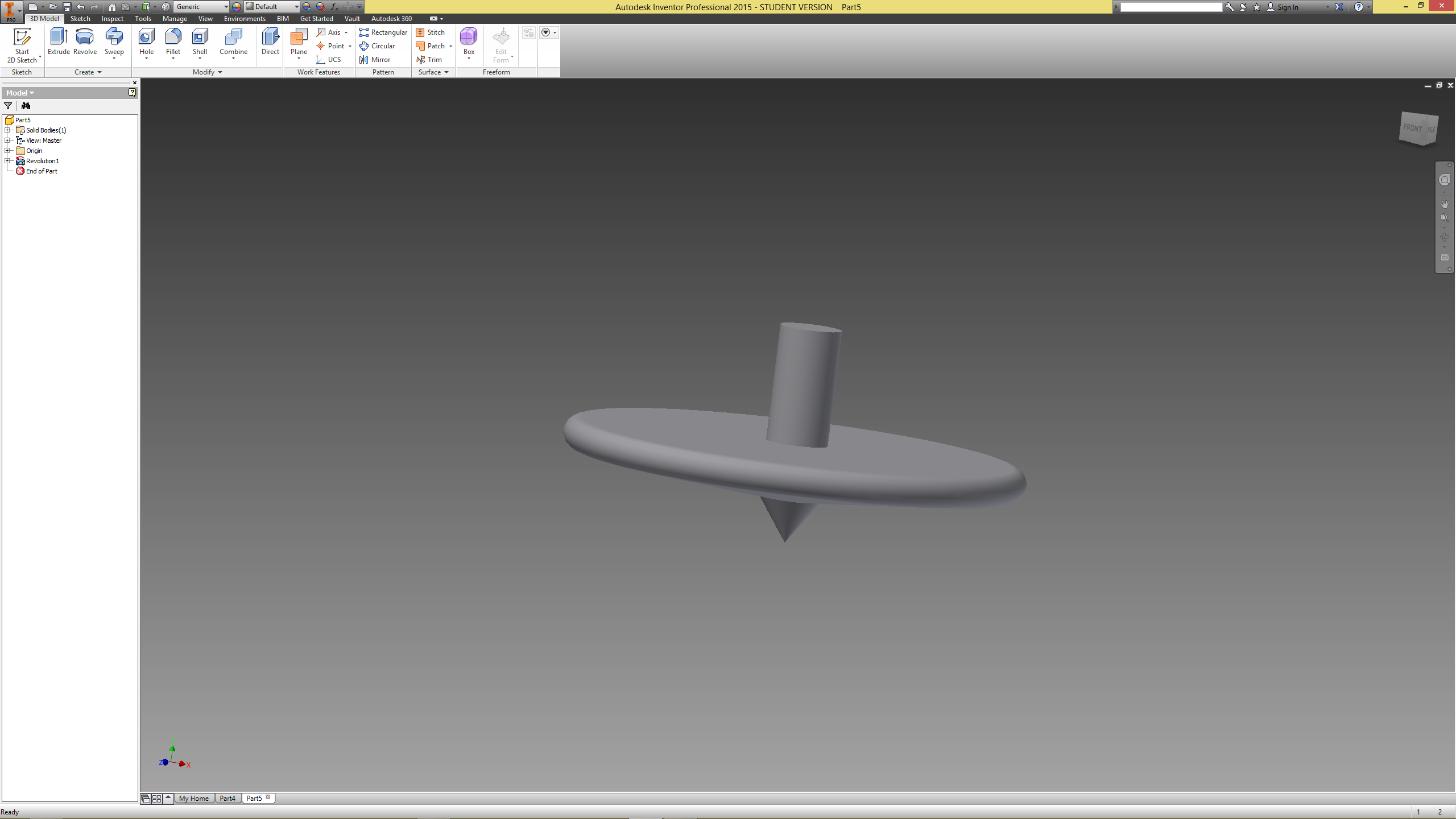
Well done, you’ve successfully completed your first 3D model in Autodesk Inventor.
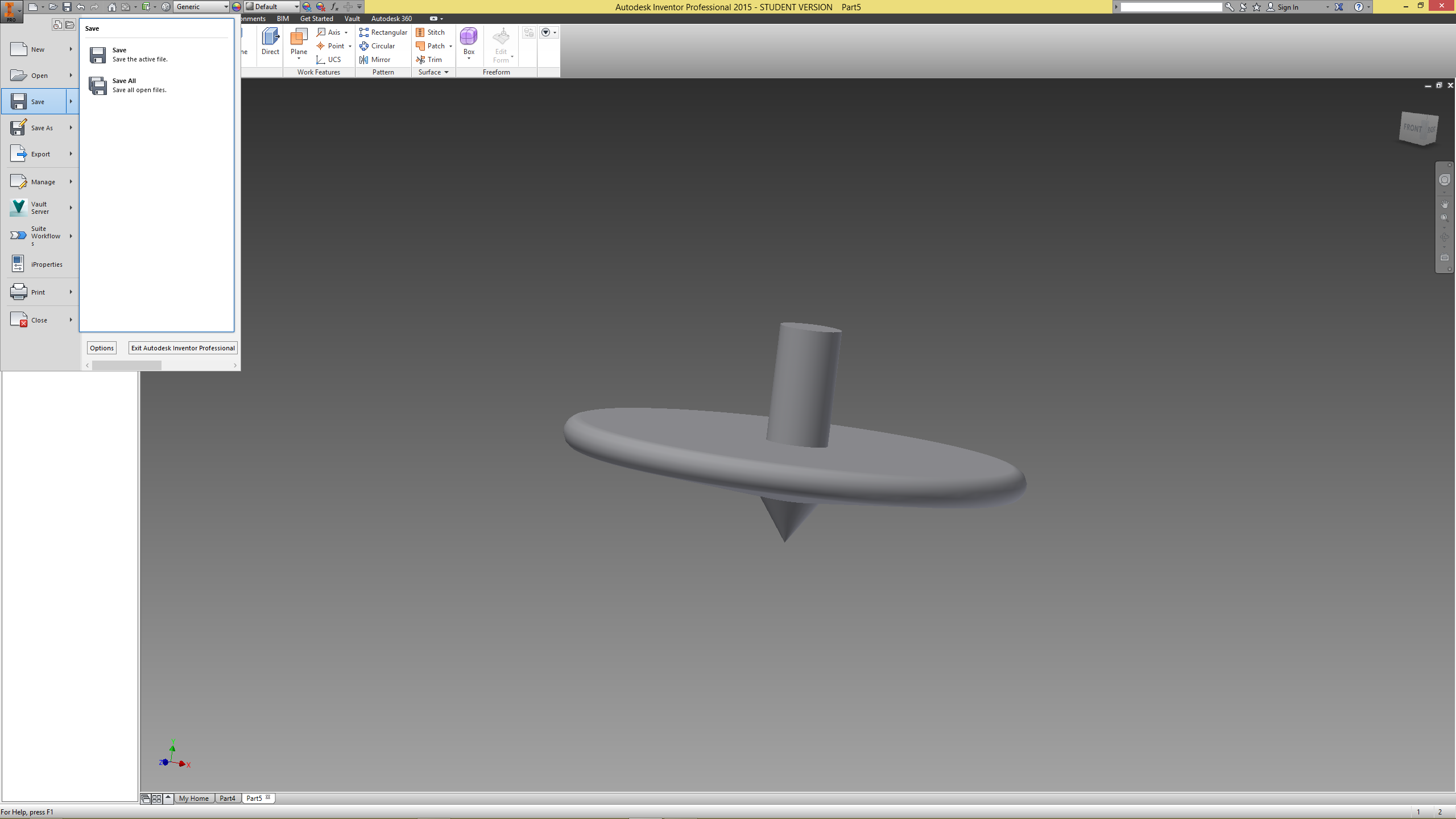
To save the model, go up to ‘I Pro’ at the top left of the screen and select save or alternatively, hold ‘ctrl s’ and name the file ‘Spinning Top’.
The last thing we’re going to show you in this tutorial is how to export the model as a .stl file, which can then be printed out on a 3D printer. Once again click on ‘I Pro’, but this time we’re going to select ‘Export’. The next step is to select ‘CAD Format’ and in the ‘Save as type’ drop down menu; choose ‘STL Files (.stl)’. Our Spinning Top is now ready to be printed.
Conclusion
As you can probably tell, this tutorial is just the absolute basics of Autodesk Inventor and it doesn’t even scratch the surface of what the program is capable of. Inventor is widely used in industry and many more complicated examples of models can be found on the internet. Have a play with some of the other commands and settings in Inventor to get a feel for the program.