A Primer on Basic on Basic Hydraulic and Pneumatic Symbols

If you look at the plan of a building or a house, you will likely encounter a hydraulic or fluid circuit. This looks similar to an electrical circuit diagram but is composed of hydraulic or pneumatic elements like pipes, pumps, and pressure gauges.
As with an electrical circuit, understanding a fluid circuit diagram requires an understanding of the symbols and the real-world hardware they correspond to. In this article, we will be going through a list of the most common and basic hydraulic and pneumatic symbols to help you the next time you encounter a fluid diagram.
Where did all these symbols come from?
The use of symbols in fluid diagrams allows them to be understood by anyone, regardless of the language they speak or understand. As such, these symbols comply with an international set of standards as created by the International Standards Organization (ISO).
In the US, the standards for hydraulic symbols are maintained by the American National Standards Institute (ANSI). There is only a very slight difference between the ISO and ANSI standards, but many American companies tend to use ISO symbols for seamless interaction with international partners.
The purpose of a fluid diagram is to provide a brief overview of the hydraulic components in a system and how they interact with each other. Details like pipe dimensions or pump capacities are typically not included or emphasized in fluid diagrams. They also do not represent the location of these components in physical space.
Despite there being dozens of standard pneumatic symbols, some facilities may still need to come up with their own symbols to serve their purpose. Some facilities modify these standards, often representing parts made up of combinations of the standard symbols. To clear any ambiguity, these fluid diagrams typically come with a catalog of the symbols that they use.
A list of basic hydraulic and pneumatic symbols
Despite plants or facilities being able to modify these symbols, a fundamental knowledge of the basic hydraulic and pneumatic symbols still goes a long way towards easily understanding fluid diagrams. After all, most of the parts of any fluid circuit will come from a selection of basic symbols – pipes, pumps, orifices, gauges, filters, and the like.
To help you develop a basic level of understanding, the following is a list of the common hydraulic and pneumatic symbols as well as a short description of the real-world parts they represent.
Hydraulic lines
| Designation | Symbol | Description |
|---|---|---|
| Piping | 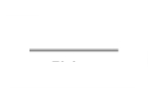 | The basic unit of a fluid diagram, the main line represents pipes through which fluid can flow. The main line operates at the standard operating pressure for the facility and is vital to its central operations. |
| Pilot line | 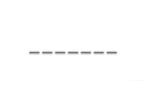 | Pilot lines are very similar to the main line except that they operate at a lower pressure. These are often used as pre-commercial production lines for relatively new products. |
| Crossing lines | 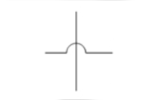 | Crossing lines denote the intersection of two lines that are not hydraulically connected. The use of crossing lines is often necessary for drawing up complex fluid diagrams. These may or may not represent lines that cross with each other in the physical space. |
| Connected lines | 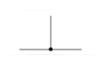 | In contrast to crossing lines, connected lines are those that have a hydraulic connection. Connected lines can be denoted with any number of intersecting lines. |
| Drain line | 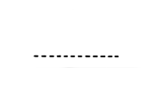 | As the name implies, this represents a hydraulic line that is directed towards the drain. |
| Flexible line |  | These are parts of the hydraulic system that are made of flexible material, typically industrial-grade composite rubber or braided steel. |
| Vented reservoir | 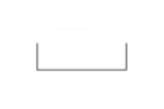 | A vented reservoir is a container used to hold the fluid in the system that is vented to its surroundings. This can serve several different purposes – as temporary storage, for pressure equalization, or to allow |
| Pressurized reservoir | 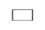 | In contrast to the vented reservoir, a pressurized reservoir allows for fluid storage at a controlled pressure. This helps in maintaining fluid pressure and composition should it contain any volatile components. |
Flow control
| Designation | Symbol | Description |
|---|---|---|
| Check valve | 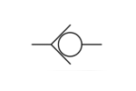 | A check valve is a type of valve that allows flow only along one direction along the line. The direction of the check valve symbol also matters – the side of the circle symbol is the side that does not allow flow. |
| Fixed orifice |  | A fixed orifice is a section of the line with a reduced cross-section, thus restricting flow. As the name implies, a fixed orifice offers no adjustability. |
| Variable orifice | 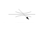 | A variable orifice, unlike a fixed orifice, has a cross- section that can be adjusted. This provides a more versatile means of flow control. |
| Ball valve | 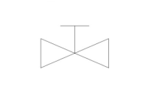 | A ball valve is a means of restricting fluid flow either partially or completely. It can be operated manually or automated via an actuator. Valves are typically represented along with their associated actuator types. |
| Level switch | 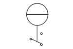 | A level switch is typically used to determine if the level of fluid in a reservoir has reached a set threshold. This can result in different outcomes such as the termination of a pump or closing of a valve. |
| Temperature switch | 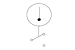 | Just like a level switch, a temperature switch is used to determine if the temperature of the fluid has reached a threshold value. Temperatures switches are more versatile and can be installed in reservoirs or along lines. They are also critical in safe pump operation to help ensure that pumps do not overheat. |
Pressure control and monitoring
| Designation | Symbol | Description |
|---|---|---|
| Pressure relief valve | 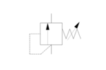 | A pressure relief valve is a valve located along the line that automatically vents to the environment when a certain pressure level has been reached. These act as both pressure control and as safety mechanisms against over-pressure. |
| Pressure gauge | 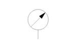 | A pressure gauge is quite intuitive – it is typically a standard gauge with pressure readings and an arrow indicator. |
| Pressure indicator |  | A pressure indicator is a less common but more basic means of showing pressure. Instead of a dial that shows pressure values, a pressure indicator only signifies if a set threshold pressure value has been reached. |
Fluid motive devices
| Designation | Symbol | Description |
|---|---|---|
| Hydraulic pump (constant) | 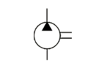 | A hydraulic pump converts rotational energy to hydraulic pressure. This symbol indicates that the hydraulic pump delivers a constant displacement volume and can only rotate in one direction. |
| Hydraulic pump (variable) | 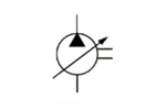 | This is a version of the hydraulic pump that allows for adjustment of the displacement volume. The diagonal arrow modifier typically shows up to indicate that the equipment can be adjusted or customized. |
| Hydraulic motor (constant) | 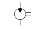 | The hydraulic motor is the opposite of a hydraulic pump – it converts hydraulic pressure to physical movements such as the rotation or lateral motion of a shaft. Many actuators are based on this principle. Again, this is a version of the hydraulic motor that operates at a constant displacement volume. |
| Hydraulic motor (variable) | 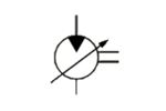 | The diagonal arrow indicates that this is a version of the hydraulic motor that is adjustable in terms of displacement volume. |
| Bi-directional hydraulic pump | 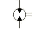 | The two triangles are used to indicate that this hydraulic pump can rotate in either direction. This means that its inlet and outlet can be interchanged. A bi-directional hydraulic pump can also have adjustable displacement volume. |
| Bi-directional hydraulic motor | 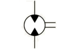 | Similarly, a hydraulic motor can also accept hydraulic pressure from either direction. This can create either of two directions of rotation. An adjustable displacement volume of a bi-directional hydraulic motor also exists. |
| Air pump | 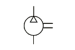 | This empty triangle symbol is used to differentiate pumps or compressors that use air as the main process fluid. |
Actuators
| Designation | Symbol | Description |
|---|---|---|
| General manual actuator | 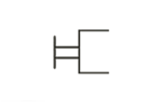 | The actuator is the mechanism by which a valve is opened, closed, or throttled. This symbol merely indicates that the actuator for this valve is operated manually but does not indicate the exact control mechanism. |
| Push-button actuator | 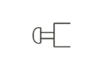 | This symbol indicates that the valve can be opened or closed using a push-button system. Although not a completely manual mechanism, an operator still has to be present on-site to push the button. |
| Spring actuator | 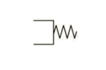 | Again, a spring actuator is simply a mechanism that allows for the easy operation of a valve. Similar to the push button actuator, a spring actuator is not considered a manual operation device but is meant for manual actuation. |
| Direct pneumatic actuator | 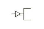 | A direct pneumatic actuator provides remote actuation of the valve. Using a pneumatic system, the valve can be controlled without any human operator on-site. |
Fluid conditioning
| Designation | Symbol | Description |
|---|---|---|
| Filter | 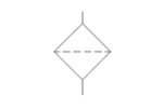 | A filter is considered a piece of fluid conditioning equipment that removes particles of a specific size from the fluid. * The diamond symbol is used for fluid conditioning devices |
| Heat exchanger | 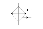 | A heat exchanger allows for heat to be transferred from one liquid to another. This is a versatile device that can be used to either cool or heat the process fluid. |
| Cooler | 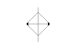 | A cooler lowers the temperature of the process fluid typically via heat exchange with the environment. In this regard, the arrows in the symbol represent heat radiating from the process fluid. |
Accumulators
| Designation | Symbol | Description |
|---|---|---|
| Gas accumulator | 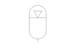 | Oval symbols are generally used in hydraulic systems to represent an accumulator for hydraulic energy. This specific symbol with an inverted triangle indicates that the accumulation medium is an inert gas that is compressed. |
| Spring-loaded accumulator | 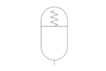 | If gas is not present, then the spring potential energy of a compressed spring can also be used for energy accumulation. Spring-loaded accumulators are simpler to operate but cannot be compressed as much as gas accumulators. |
| Weighted accumulator | 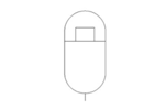 | A weighted accumulator uses a series of weights to provide compression to a fluid. A huge advantage of weighted accumulators is that they can deliver stable and constant pressure release until the fluid in the cylinder has been depleted. |
Cylinders
| Designation | Symbol | Description |
|---|---|---|
| Differential cylinder | 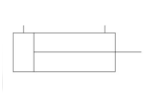 | A differential cylinder is a mechanism that uses hydraulic pressure to create the linear movement of a piston. Hydraulic fluid can be introduced to either side of the piston, allowing its rod to be pushed or pulled. |
| Ram | 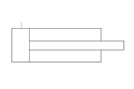 | A ram puts more emphasis on the girth of the rod, representing it with a rectangle instead of a line. The primary purpose of a rod is to provide a pushing motion, thus it is designed to have only a single inlet for hydraulic fluid. |
This list is by no means exhaustive of all the possible symbols used in fluid diagrams – there are probably a few dozen standards symbols that we have not covered. Still, you should be able to understand the bulk of any fluid diagram using just the symbols here.
Final thoughts
Fluid systems can get very complex, especially in industrial and manufacturing facilities, and even in large commercial buildings. For this reason, it is always a good idea to have a fluid diagram that makes it easy to understand the system or pinpoint the root cause of a problem.
For those with industry experience, a lot of these symbols may already seem very familiar. As those people can attest as well, understanding a fluid diagram goes way beyond just knowing the symbols.