What is Drawn Material? The Fundamentals of Metal Drawing

We’ve written about the common processes using manufacturing and have even written in great detail about forging and the use of drop hammers. This barely scratches the surface of the manufacturing industry – an industry that has grown in leaps and bounds through the decades to serve evolving customer needs.
In this article, we will focus on drawing, which is a common way of working with sheet metals, wires, and tubes. How exactly does drawing work and what are its advantages to other manufacturing processes? What products are considered drawn materials?
Metal drawing – a tensile forming process
Drawing is a metalworking technique classified under forming, or the deformation of a material by the application of forces to the desired shape without the addition or removal of any of the material. By this logic, it relies on the principle of plastic deformation, or the property of a material to be deformed to any shape by the application of a force that overcomes its tensile strength.
More specifically, drawing requires the application of tensile stress to the metal. Although it’s traditionally a metalworking technique, drawing has since evolved for use in working with plastics or glass.
Most drawing techniques use a combination of compressive and tensile forces to achieve deformation. However, the overall effect of the process is a stretching of the original material. This is the primary characteristic that distinguishes tensile forming to forming techniques that use compressive forces, such as extrusion and forging.
Drawing is a highly specific technique that is suitable only for specific types of feedstock. Central to the concept of drawing is the act of pulling material through a die, although this may not necessarily be the case in all circumstances. Drawing is typically done cold, although metals can be also be heated prior to drawing to reduce the amount of tensile stress needed.
Types of metal drawing
The techniques of metal drawing are so different from each other that they need to be classified into sub-categories. It’s easiest to separate these techniques based on the type of feedstock they use.
1. Sheet metal drawing
In sheet metal drawing, a piece of sheet metal is deformed to the desired shape by using a hydraulic or pneumatic punch with a built-in die assembly. The objective of the technique is for the material to be drawn radially into the die, so an even and sustained application of pressure is essential. Lubrication also needs to be applied to the stock metal to allow it to flow into the die.
Sheet metal drawing can be classified as either shallow drawing or deep drawing. The difference lies only in the dimensions of the part that is being “drawn” or deformed. If the desired deformation is longer than the diameter of the sheet metal stock, then it is considered a product of deep drawing. Otherwise, the process is considered shallow drawing.
The process of sheet metal drawing needs to hit a delicate balance to achieve products that are perfectly smooth yet mechanically stable. Too little deformation can end up with the drawn material having a wrinkled appearance. On the other hand, deforming the sheet metal by too much can result in the material getting stretched too thin or getting ruptured.
Products made by sheet metal drawing are incredibly common. Basins, mixing bowls, or any thin metal products with a dome-like profile are likely made via sheet metal drawing. This is a very fast process typically employed for mass production.
2. Wire drawing
Wire drawing is a process in which an existing stock wire is stretched to reduce its cross-section and to increase its length. This is done by drawing the wire through a series of progressively smaller dies. Although the process is very similar to extrusion, the prevailing force that causes the deformation is a pulling force, instead of one that pushes.
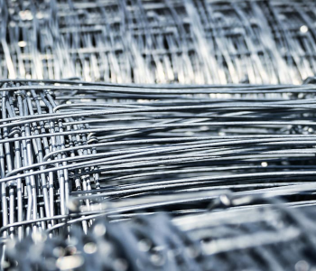
With the massive amounts of wire used in commercial and industrial applications, wire drawing considered one of the major industrial processes. A wire can be drawn to extremely small diameters as low as 0.0001 inch.
To start the wire drawing process, its leading end is either tapered or hammered to allow it to pass through the smallest die in the series. The wire can be wound into a spool after the die, which can also rotate to provide the force the pulls the stock wire. One wire can go through several intermediate stages, between which they can be annealed to enhance ductility.
Wire drawing is a very fast method of producing wires of fixed dimensions. It is highly accurate and typically requires no post-processing. The compressive forces exerted by the die also enhances the strength of the drawn material, especially when the wire has been cold-drawn.
3. Bar drawing
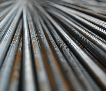
Much like wire drawing, the objective of bar drawing is to reduce the cross-section of a bar by drawing it through a die. Since it is not possible to pull a bar by coiling it around a spool, it is instead clamped on a moving element of a draw bench. The clamped section moves via a chain drive, slowly pulling the bar through the die. Alternatively, a column of hydraulic fluid can also be used to drive the moving element.
Just as with other drawing techniques, lubrication between the die and the stock bar is an essential part of bar drawing. The cross-sectional area reduction is typically limited to only 20% of the original area, although higher numbers can be achieved depending on the material’s ductility.
If a single pass is not enough to achieve the desired dimensions of a bar, multiple passes through different-sized dies can be done instead. Annealing may also be done in between successive drawing stages to increase the ductility of the material.
4. Tube drawing
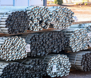
Tube drawing is a lot like bar drawing, except a tube comes with an internal cavity. Thus, there are two dimensions to be considered – the cross-sectional area of the internal cavity, as well as the area of the whole tube.
Tube drawing also requires a chain-drive or hydraulic-driven bench where one end of the tube is hooked or clamped on a moving element. The size of the die determines the cross-sectional area of the tube. To control the size of the internal cavity, a mandrel is inserted inside the tube which will compress the material against the die. This mandrel can either be fixed or floating.
The pros and cons of metal drawing
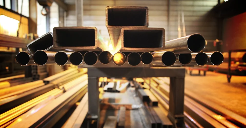
From what we’ve seen so far, it’s apparent how far-reaching the influence of the metal drawing process is. Just about all electrical wires, metal bars, pipes, tubes, and sheet metal products have gone through some form of metal drawing. What makes it such an ideal technique and what are its limitations?
PROS
Fast
Once the metal drawing equipment has been set up, it’s pretty much just a matter of placing the feed stock for the whole process to run. This makes metal drawing particularly compatible with high-volume mass production and even be integrated into automated control systems. With automation, metal drawing can be modified for higher throughput, more consistent quality, and lower labor costs.
Creates strong and seamless parts
The phenomenon of strengthening may not be applicable to sheet metal drawing, as it stretches the material and reduces its wall thickness. However, the advantage of sheet metal drawing is that it can create products with complex geometries from a single stock metal sheet. This means that the products have a seamless construction, making them perfect as leak-proof containers.
The benefit of “work hardening” is more fully realized in wire, bar, and tube drawing. This enhances the strength of a part while achieving the desired geometry – a two-fold advantage.
CONS
Difficult and costly to set up
The reliance of metal drawing on precision-machined dies makes the initial set up a tedious and time-consuming process. Since the die dictates the quality and dimensions of the finished part, it has to be made with extreme accuracy by a highly skilled metal worker. Thus, it takes significant work and expenses to start a metal drawing process.
Highly specialized equipment
Metal drawing machines are not known for their versatility. Once a press or draw bench has been assembled with a die, it’s pretty much set up to make a specific part and that part only. Dies can be replaced, but this will require significant downtime. The most optimal use of metal drawing technology is for the continuous manufacturing of a single product with permanent dimensions.
Metal drawing applications
Deep drawing of sheet metal is a highly vital industrial process for creating high-precision thin-walled parts. It is the perfect technique to create housings for electronics and sensors since their seamless characteristics make them impermeable to moisture and suitable for high-pressure environments. There are also a lot of components used in automobiles, aircraft, and medical devices that are made using deep drawing.
Wire drawing hardly needs any explanation – just about all wires used for electricity and data transmission are made via wire drawing.
Metal bars and tubes made via metal drawing are a bit harder to identify because there are a lot of other manufacturing processes that can make the same products. In general, metal drawing is the go-to method when a manufacturer wants parts with superior dimensional accuracy and surface finish.
Final thoughts
Metal drawing is one of the more specialized examples of manufacturing processes. Although its scope is small, it undoubtedly creates parts with superior mechanical properties. Its industrial relevance also cannot be discounted – it’s the go-to manufacturing technique for many of the most important parts and components of modern industries.