Electrical Actuators – What They Are and How They Work

Automating any process is easy if all you need are electrical signals. We’ve already written about how programmable logic controllers (PLC) can receive an input from a sensor, run the parameters through a pre-programmed algorithm, and determine an output. But what If there are steps in the process that require manual movement?
This is where electrical actuators come in. In a nutshell, an electrical actuator’s purpose is to convert an electrical signal into physical motion. How exactly does an electrical actuator work and where can you find it in a standard industrial process?
What is an electrical actuator?
The primary purpose of an actuator is to convert an electrical signal into kinetic energy, thus integrating parts that require mechanical into an automated process. An electrical actuator can either create rotational or linear motion, depending on the type of instrument to which it is installed.
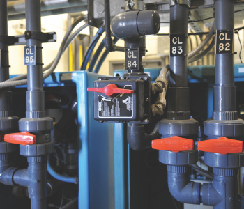
Electrical actuators are typically found in the various types of valves used in industrial facilities for controlling the flow of liquids or gasses. An electrical actuator can be set up to either regulate the flow of a fluid in a valve or simply to toggle between the open and closed positions. There may also be more specialized uses of electrical actuators such as clamps, flaps, or conveyors.
The mechanism of electric actuators may vary from one type to the next but there are three basic components to its operation: an electrical signal, a power supply, and a moving mechanical shaft. The electrical signal coming from the PLC directs the power supply to active or deactivate the force that drives the motion of the mechanical shaft. As we shall see later, the specifics of this process can differ across different types of electric actuators and valves.
Types of electrical actuators and how they work
To narrow the scope of the discussion, we shall limit this section to electrical actuators used with valves. After all, these are the most common and the most relevant across virtually all industries.
1. Spring and diaphragm actuator
A spring and diaphragm actuator is a pneumatically driven actuator that is used for granular flow control in globe valves. The valve element, connected to the mechanical shaft, is moved into position by an expanding diaphragm. This expansion is caused by a pressurized air supply that, in turn, is controlled by another set of electrical actuators.
The combination of this type of actuator and a globe valve offers a unique level of flow control. Globe valves, in particular, are used in a lot of industries to regulate fluid flow by controlling the degree to which they are opened. In turn, the expansion of the diaphragm that pushes on the mechanical shaft is controlled simply by regulating the pressure of the incoming air supply.
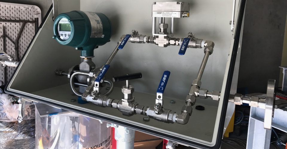
The requirement to control measure introduces another layer of complexity to a spring and diaphragm actuator. This means that a pressure sensor needs to be installed on the air supply line, providing feedback to the PLC in an open-loop architecture. When deviations to the target pressure observed, the PLC responds accordingly by increasing or reducing the air supply.
For redundancy, a dial-type pressure gauge is often installed on the air supply line as well. This allows operators to manually check the pressure values, should there be uncertainties on the sensor value.
A spring and diaphragm actuator can be considered an indirect way using electrical signals to control the mechanical valve movement. The electrical actuator, in this case, applies only to the air supply opening. However, the precise control of air supply is the driving force that allows for the granular movement of the diaphragm and the mechanical shaft. A spring and diaphragm actuator is a critical part of any fluid line that requires a precisely controlled flowrate.
Despite its benefits in flow control, the major drawback of a spring and diaphragm actuator is that it’s hard to maintain. With more moving parts than other actuators, there is a higher chance of something going wrong with a spring and diaphragm actuator. However, this should not be a problem if the operation of the actuator is done within acceptable parameters and regular maintenance schedules are followed.
2. Solenoid actuator
A solenoid actuator consists of a coil connected to a power supply that is wrapped around the mechanical shaft of a valve. The mechanical shaft and the coil are very close to each other but are otherwise not in contact. The shaft is then connected to the valve element.
Solenoid actuators do not provide fine granular control and are more suitable for valves that only need to be either at the open or closed position. For this reason, solenoid actuators are typically found in tandem with gate valves. The action of the actuator results in the rapid movement of the mechanical shaft, allowing for quick deployment or withdrawal of the valve element.
The working principle of the solenoid actuator is based on Ampere’s Law. The law states that an electrical current moving along any conductor creates a circular magnetic field. This effect can be compounded by orienting the conductive material in a coil.
With enough turns, electrical current transmitted on a coil can create a magnetic field strong enough to induce the motion of a magnetic body. In the case of a solenoid actuator, the mechanical shafts act as the body that moves in reaction to the produced magnetic field. The strength of the current supply to the coil can influence the strength of the magnetic field, and thus, the speed at which the valve opens and closes.
The strength of a solenoid actuator lies in its simplicity. With the solenoid being the only element that induces motion, solenoid actuators are fairly easy to take apart, maintain, or troubleshoot. However, solenoid actuators are limited to creating linear motion. This mechanism is typically not used for rotary actuators.
3. Electrical motor actuator
An electrical motor actuator is the simplest of the three types we have discussed here. As its name implies, the driving force of this actuator type is an actual electrical motor. The rotational motion of a motor can be translated to the linear or rotational motion of a valve’s mechanical shaft depending on the gear train connected to it. This means that electrical motor actuators can be installed across a wide range of valve types – globe valves, gate valves, and butterfly valves are the most common.
The degree of granular control that is possible with ana electrical motor actuator depends on the type of motor and the design of the gear train. In most cases, this type of actuator has a stepper motor that can move in fixed and discrete steps. Conversely, a servomotor package can also be used that combines an electric motor with a gear train that is designed to convert multiple rotations of the motor shaft into higher torque rotation for the valve.
A unique application of electrical motor actuators is for the remote operation of multi-turn valves, such as globe valves with threaded stems. For just about all uses of electrical motor actuators, a brake has to be installed above the motor to prevent the forced opening of the valve caused by the fluid pressure. Not having a brake will result in the premature degradation of the motor and actuator because of constant and rapid oscillation between the closed and open positions.
An electrical motor actuator is one of the most versatile actuator types, allowing for both linear and rotary actuation and granular control. It doesn’t close or open a valve as rapidly as a solenoid actuator and is more prone to being dislodged from its desired position due to fluid pressure.
Having a motor drive the actuator also means that it’s harder to maintain – servicing the motor means having to replace it with another if the operation needs to continue. Another disadvantage is that the motor itself is quite big. For facilities with limited space, installing an unplanned electrical motor actuator may be challenging.
Pros and cons of electrical actuators
As we’ve seen from the discussions of the different actuators, each actuator type has a unique set of advantages and disadvantages. Looking at electrical actuators as a whole, however, reveals that there also certain tradeoffs to their benefits:
PROS:
Suitable for PLC integration
The reliance on electrical signals makes electrical actuators a perfectly suitable component of a PLC system. Through its various I/O modules, a PLC communicates with its several external components via electrical signals. Any feedback signals are then transmitted back to the PLC and processed through a pre-programmed algorithm. This is instrumental for ensuring that valves are opened and closed as desired and that the target flow rates are achieved.
Scalable and versatile
For both solenoid and electric motor actuators, the current supply can be varied to control the speed at which the mechanical shafts move. This means that an actuator’s parameters can be adjusted to influence valve behavior as needed. It also means that a single actuator can be installed to several different valves, should it be necessary when conducting an overhaul of the existing process.
Can be reprogrammed easily
Integration into a PLC system means that the behavior of an electrical actuator can be changed by changing its I/O module or making changes to the PLC’s programming code. This is crucial for industries that require frequent tweaking of process parameters and helps the PLC system attain the level of versatility for which they are known for.
CONS:
Not suitable for all environments
The reliance on electrical systems, wires, and conductors necessarily means that electrical actuators are not suitable for environmental conditions. Exposure of these components to extreme temperature or humidity may result in rapid deterioration and more frequent repair and maintenance. For these harsh conditions, actuators that rely purely on pneumatics or hydraulics may be more appropriate.
Expensive
Shifting from mostly manual process flow to pure automation is a huge endeavor, both in terms of effort and financial expenses. The contribution of actuators is a huge cost driver, especially because a 1:1 relationship needs to exist between each valve and each actuator. Installation of the actuators, the wiring, and the corresponding PLC system will take a lot of time and expert services.
Final thoughts
Electrical actuators are an essential part of any automated industrial process. If the PLC acts as the brain of the system, think of the electrical actuators as its many hands and feet. In fact, this is the perfect analogy because a system’s PLC also received feedback signals from the actuators to check if they are working as intended.
To put it briefly, electrical actuators convert electrical input into mechanical motion. As we’ve described here, there are a few different mechanisms for achieving this, not all of them using electricity in a very direct way. However, all these different types of electrical actuators are valuable as illustrated by their widespread use across several industries.