How to Design an Injection Mold

What is injection molding?
Injection Molding is a commonly used technique in manufacturing. It is especially useful when one needs to manufacture large volumes of the same item. Injection molding allows the manufacturer to repeatedly create the same product with the same specifications, a good level of tolerance, and cost efficiently. All kinds of household items such as appliance housings, bottle caps, plastic parts, and auto parts are manufactured using the process of injection molding.
The process of injection molding involves pushing a melted plastic mixture under a certain pressure through a cavity of a tightly held mold. The mold is also under a certain clamping pressure depending upon the viscosity of the plastic fluid being injected. The molten plastic flows inside the mold and takes the shape of the mold. Then, the plastic is allowed to cool down and set. Finally, the mold is opened up and the solidified plastic part is pushed out using ejector pins.
The mold material
The mold used in the manufacturing process is generally made of steel, aluminum, pre-hardened steel, or a beryllium-copper alloy. The cost of making a mold influences the material which is used to create the mold. Steel is normally more expensive than other materials. However, the benefit with steel is that the lifespan of a steel mold is longer.
Aluminum molds do not cost as much as steel molds. Production cycles with aluminum molds are faster because aluminum dissipates heat better than steel. Beryllium-copper molds are used in applications where shear heat gets generated in high proportions and fast removal of heat is necessary.
Designing the mold
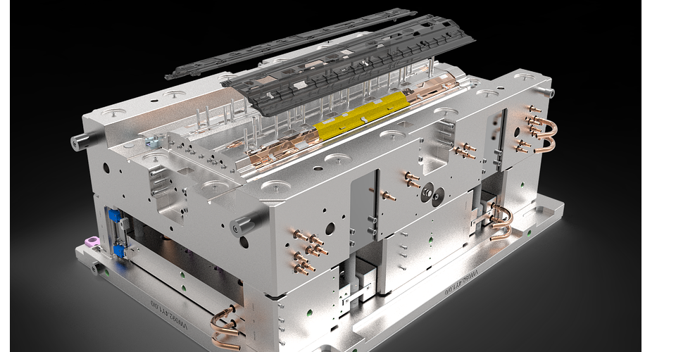
The mold used in injection molding is composed of two halves. They are known as the cavity side (side A) and the core side (side B). The core side is where the ejector plate and ejector pins are located. Once the molten plastic solidifies, the side A moves up and the side B then ejects the part resting on it using ejector pins.
One of the downsides of using the injection molding process is its high initial cost. Even though the per unit product cost for injection molding is low because of its repeatability and the resulting economies of scale, the mold set-up cost is quite high.
Once the mold is made, changing it at a later stage tends to be prohibitively expensive. Hence, the mold is to be designed perfectly before starting any production batch. There is a need to get things right the very first time. The following are some guidelines or best practices that need to be followed by mold designers in order to avoid some of the most common issues faced by manufacturers in the injection molding process:
Wall thickness variations
Changing wall thicknesses in the mold can lead to problems like warping or bending of the part being manufactured. The surface of the part comes out uneven and not flat, as was intended. It is always preferable to have a uniform thickness throughout the mold surface.
If varying thickness necessary, then it should be ensured that the transition between two sections of varying thicknesses should be smooth with the use of fillets or chamfers. The idea is to let the molten material flow evenly when injected. Uneven flow is what causes problems.
Also, thick sections should be kept to a minimum or completely avoided if possible. Normally, a safe level of thickness hovers around the 1.2mm to 3mm mark. Most materials used in injection molding tend to behave well with such thicknesses.
Rough edges
The edges of the mold influence the edges of the part being made. Sharp edges can cause stress concentration and weaken certain portions of the manufactures part. Hence, it helps to have smooth edges, both on the inside and outside surfaces of the mold.
A bend radius of 0.5 times the mold wall thickness is a good measure of the smoothening for the inner surface of the mold while a bend radius of 1.5 times the mold wall thickness works well for the outer surface of the mold.
Hollowing out thicker sections
It is better to have hollow sections rather than blocks of thick sections. Thicker segments tend to cause warping and sinking. Hollowing out sections does not mean that you have to compromise on the stiffness and strength. By incorporating ribs in the design, you can create a hollow part which is just as strong and stiff.
Having thinner walls also mean lower weight and lesser material consumed. Ribs used to create hollow designs are recommended to have a maximum thickness of 0.5 times the wall thickness and a height of a maximum 3 times the wall thickness.
Reducing drag marks through draft angle
High friction between the mold surface and the manufactured part while ejection can cause scratches and drag marks on the manufactured part. This is especially true when the wall of the mold is vertical.
To prevent such marks and for easier removal of the part, a drag angle is added to the walls of the mold. A draft angle of about 1 degree is recommended for every 25mm of thickness of the manufactured part. The draft angle can then be increased proportionately to the increasing thickness of the part. If you are looking for a nice textured feel on our part, then increase the draft angle by an extra one or two degrees.
Part lines
The interface where the two halves of the mold meet leads to part lines on the manufactured part. The part line is a physical line which is clearly visible on the part as it protrudes out slightly from the surface of the part. These lines need to be strategically placed such that they do not affect the appearance of the part significantly. Normally, the part is designed in such a way that the part lines appear on the sides of a part rather than on the front or back face.
The gate
The gate is the small opening from where the molten material is injected into the mold. The gate design, its location, and the type of gate used are all important because those choices affect the creation of the manufactured part.
The most commonly used gate is the edge gate. As the name may imply, edge gate is located at one edge of a part being made. It leaves a gate mark at the parting line of the part. This gate type is a good fit for flat parts with medium and thick sections.
The next type of gate is the sub-gate. The main benefit of using the sub-gate is the fact that it allows the gate mark to be away from the parting line. Certain parts may require that sort of design. It is an automatic trimming style of gate.
Next gate is the hot tip gate. This gate is situated at the top of the part and is ideal for round, cylindrical, or conical shapes. The gate mark, in this case, will be at the top surface of the part.
Lastly, we have the sprue gate which is a low-cost low-maintenance gate. It is good for use with parts that are cylindrical and need symmetric filling.
Whatever gate type you decide to use, always remember to keep gates away from the cores and the pins. This will allow the molten material to flow freely without any obstructions. To avoid sink marks or voids, try to place the gate near the heaviest cross-section of the part.
Also, remember that large gates allow a higher flow rate and hence consume lesser time while smaller gates allow lower flow rates and take more time. The manufacturing of large parts should involve the use of larger gates. Smaller gates may also require higher injection pressure. However, smaller gates give a nicer appearance to the part.
Designing guidelines for some common features
Now let us look at how some of the more common features are designed and implemented using the injection molding process:
Adding threads
Adding threads to injection molded parts can become quite tricky, especially if the threading is included in the designing phase of the part itself. Threads would essentially be treated as undercuts by the injection molding machine and that adds significant cost to the entire process. Hence, designing parts with a thread on it is not recommended.
The other two options are using inserts or bosses. Bosses are quite common as they resemble ribs which close on themselves, or a cylindrical projection which has holes for the screws to fit in. The boss should be designed such that the outer diameter is at least 2 times the nominal diameter of the screw which will fit into the boss.
Inserts can be added to the injection molded part via in-mold insertion, thermal insertion, or ultrasonic insertion. The good thing about using inserts is that you can assemble and disassemble them across multiple cycles. In a way, it provides some flexibility of use.
Text and logos
Manufacturers often emboss text on the manufactured part. Text can be used to depict company names, logos, instructions, and warnings. It is often easier to emboss text rather than engrave it on the part one-by-one after completing the injection molding process.
Embossing text simply requires using a CNC machine and machining the letters on the mold itself. This method is economical as the cost of machining gets spread out over the entire volume of all the production batches. A height of 0.5mm above the surface of the manufactured part makes the text legible enough to read.
Living hinges
Living hinges are very common among household plastic items such as trash cans, containers, and bottles. Living hinges basically connect two segments of an injection molded part and allow those segments to bend in and out. It is quite normal to have living hinges with a lifecycle of a million bends/flexes.
When making living hinges, make sure you use a flexible plastic such as polyethylene or polypropylene. Nylon is also often used to make the hinges. A minimum thickness of 0.2mm to 0.35mm is recommended. Increasing thickness results in a stronger hinge but a stiffer one too. Also, make sure that the hinges are not stretched out too long. If the hinge length exceeds 150mm, then it is better to split up the single hinge into two shorter hinges.
Crush ribs and snap joints
Snap joints are small protrusions that remove the need for fasteners in joining two parts together. Crush ribs are small bumps or projections which add friction when two parts need to be secured together. Both can be made via the injection molding process using certain specific (and sometimes polar opposite) guidelines.
First, a draft angle needs to be added in case of snap joints. In the case of crush ribs, however, a draft angle is not needed. Snap joints should have a thickness of 0.5 times the wall thickness on the mold. In case of crush ribs, you need to have a 0.25mm interference distance between the crush rib and the fitted part.
Guidelines for various types of surface finishes
Often times, the type of finish on a surface is quite important. It is influenced not just by aesthetic requirements, but also by technical specifications. For example, a glossy finish may be needed for making the product appear a certain way while a rough finish may lengthen the life of a part which will slide/roll and repeatedly come in contact with other parts.
Texturing or applying certain types of finishes can also hide flaws and imperfections that would otherwise be visible on the surface of the manufactured part. Certain types of finishes can hide fingerprint marks from the surface as well. So, there are plenty of functional uses of surface finishes.
Certain steps need to be taken before starting the injection molding machine in order to achieve a particular type of finish. Guidelines for preparing the mold in order to achieve common types of surface finishes are as follows:
Glossy finish
A glossy finish is possible when the surface of the injection molded part is extremely smooth. This smoothness can be obtained by polishing the inner walls of the mold. The mold is first smoothened and then polished using a diamond buff. This procedure is done until the walls of the mold give a mirror-like appearance.
If a lower degree of glossiness is required, then the mold is smoothened using fine grit sandpaper. Such treatment results in the manufacturing of parts which have a good appearance which isn’t shiny or glossy. It should be noted that the choice of material also affects the glossiness of the final product. Acrylonitrile Butadiene Styrene has more of a glossy feel to it than Polypropylene does.
Matte finish
One of the most popular finishes is the matte finish. It is commonly seen on designer bottles, phone covers, auto parts, and other everyday items. In order to create a product with a matte finish surface, the mold is smoothened using fine stone powder. This gives a nice rugged feel to the inner wall surface. This process of smoothening also removes machining marks which may have remained on the mold post its creation.
Textured finish
Certain plastic items have a textured finish which is possible because the mold used to create those items is smoothened using fine stone powder and then sandblasted.