Understanding Press Fit and Press Fit Tolerance

Joining components together in a manner that is safe, reliable, and takes advantage of material properties is one of the primary areas of innovation in manufacturing industries. One such technique is called press fit – a method that relies on friction and requires no soldering, welding, or machining of the parts.
As you will see later on, press fits are some of the most precise examples of fastening two parts together. Although they make very strong parts, this method isn’t exactly suitable for all scenarios. Read on as we cover the basics of press fits and define press fit tolerance.
What is press fit?

A press fit, sometimes known as an interference fit, is a method of joining two tight-fitting parts that rely on friction. This is one of the most preferred fastening methods for applications that require a lasting bond and perfect alignment. The process typically does not require exposure of parts to extreme temperature, requires no soldering, and is compatible with automated systems.
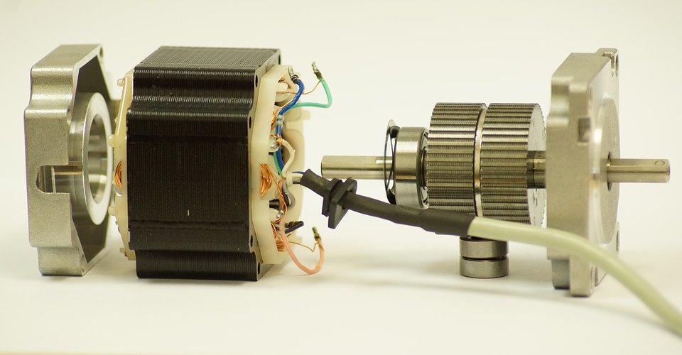
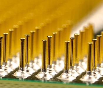
In any press fit application, there are two mating parts that join together in a very tight manner. These two mating parts can take different forms. The most common example would be a shaft and a hole, but press fits are also used for smaller components such as the electrical terminals on a printed circuit board (PCB). Press fits are ideal for joints that involve electrical components as the close fit of the parts ensures reliably conductive contact.
Due to the large friction forces involved, pressing together of the two mating parts is typically done by a hydraulic or pneumatic piston. This is a slow and deliberate process that is focused more on alignment than impact.
Press fit technology has become widely used because of its reliability and relative simplicity. Although it demands very exacting measurements on the mating parts, the actual execution of mating components together can be carried out even without an exceptional level of skill.
How a press fit works
To understand how press fit works, we first need to describe the physical characteristics of the two mating parts. For the basic example of a shaft and a hole, it is critical to realize that the hole is slightly smaller than the shaft.
When the shaft is pressed into the hole, the material of the shaft undergoes slight compression. This induces the shaft to exert a normal force onto the inner surface of the hold. At the same time, the hole presses inward, as it also goes through a slight expansion because of the insertion of the shaft. This normal force contributes to the generation of a large friction force which holds the two components together.
The actual magnitude of the normal force exerted by the hole and shaft components depends on the material that they are made from. Hard metals, such as steel, are more resistant to deformation and will exert a greater normal force. On the other hand, plastics and soft rubber will generate smaller normal forces on account of their propensity for deformation.
The press fit tolerance, which we’ll discuss in more detail later, is a measure of how much the shaft is “over-sized” compared to the hole. This measures the amount of compression or expansion that the material must endure, and how much normal force they exert.
Best practices in designing press fits
As with just about any industrial process or technique, a press fit isn’t an all-around solution for all fastening needs. If you are considering using press fits, here are a few rules of thumb to keep in mind:
Material selection and compatibility
The fastening ability of a press fit relies on the ability of the material to hold a constant normal force as a reaction to its deformation. However, there are materials that naturally deform when subjected to a constant force or “flow” into a new orientation. When these types of materials are used in a press fit, they tend to lose friction over time thereby loosening the grip of the fastened parts.
Soft plastics, such as nylon, polyurethane, and polycarbonate are good examples of materials unsuitable to press fit. This is also the reason why most plastic parts instead have a “snap fit” connection that relies on a locking mechanism rather than sustained tension.
Anticipate temperature variations
Almost all materials react similarly to changes in temperature – objects expand when heated and contract when cooled. However, the degree with which these phenomena occur will depend on the material in question. For instance, a piece of aluminum will expand by a larger margin when exposed to high temperatures compared to an equivalent piece of rubber.
This disparity in thermal expansion and compression behavior will matter if we have a press fit assembly made of two different materials. Expounding on our previous example, an assembly made of a rubber shaft inside an aluminum hole may end up losing its grip when subjected to extreme heat.
To be clear, it’s perfectly acceptable to join two different materials together as long they either do not need to be exposed to extreme temperatures or have similar coefficients of thermal expansion.
Part alignment is key
The alignment of parts joined using press fits has very small tolerance. A perfectly aligned assembly should have internal forces that are evenly distributed, ensuring that the parts will remain held together even when they are subjected to strong vibrations.
For this reason, manufacturers have come up with many means to achieve perfect alignment. Proper tooling and fixturing are critical factors in this step. Most manufacturers would design the mating parts to have knurls or matching pairs of projections and indentations. This ensures that parts will mate together perfectly with little room for error.
Although the hydraulic or pneumatic presses used to combine parts for press fits require a lot of power, they are typically operated very slowly. This gives allowance for realigning of the parts as they are pressed together. Ideally, operator intervention will not be necessary but can be done if the situation calls for it.
Consider tapering the mating part
A common strategy when designing parts for press fits is to taper the end of the shaft. This is called a chamfer and helps with both the alignment of the parts and the even distribution of force around the circumference of the hole. Pressing together of the parts is also made easier and smoother by the addition of a chamfer, as the compressive forces tend to build up more gradually.
Determining the proper press fit tolerance
The magnitude of normal force will also depend on how much of the material compresses or expands once they are fastened. Recall that the shaft is typically a little larger than the hole. This difference in dimensions is what is typically referred to as the “press fit tolerance.” This is a very small number, typically less than 1/1000 of an inch.
The appropriate figures for press fit tolerance takes into consideration the dimensions and material of both the shaft and the hole. For instance, rubber parts will require a higher tolerance as they have a greater propensity for deformation. The tolerance also increases with increasing size of the part, although this relationship may not necessarily be linear.
Unfortunately, the calculations for determining the proper tolerance for a press fit assembly are far from straightforward. Aside from the dimensions of the shaft and hole, including chamfers at either side of the shaft will also cause a shift in the values. The intended operating temperature for the part being assembled also needs to be considered.
If a part contains more than one pin, the tolerance may also need to be adjusted with consideration of the maximum compressive force of the hydraulic or pneumatic press that will be used.
The difficulty of calculating proper press fit tolerance is the biggest challenge of including such technology in an automated assembly line. If undetected, a misaligned press fit or one with too large a tolerance may damage either the part being assembled or the pneumatic press. With the magnitude of forces involved, such an accident could be quite catastrophic.
Shrink fit – an alternative to press fit
Despite the many benefits of press fits, the fact that it hasn’t replaced all mechanical connections is proof enough that it’s not perfect. One of the more popular alternatives to a press fit is a shrink fit. With this method, the dimensions of either of the two parts being assembled are altered via heating or cooling.
The idea behind the method is to use thermal expansion to more easily join the two parts together, after which they are brought back to room temperature. Tolerance is still critical in this technique but is much more forgiving. It also lessens the force that a hydraulic or pneumatic press must exert to bring the two parts together.
The drawback of this technique is that it takes a longer time on account of having to heat up or cool down the parts to extreme temperatures. There’s also a ton of specializes equipment involved. Before a shrink fit can be done, metal parts are either heated to temperatures of up to 300 °C or cooled down with liquid nitrogen. There’s definitely a bit more technical skill needed all for the sake of fastening the two parts together in a manner that is more reliable than a press fit.
Final thoughts
On the surface, a press fit seems like a very simple way of joining together two components to create a singular part. It’s quick, reliable, and does not require soldering or machining. However, there are so many things that can go wrong with a press fit assembly. A properly done press fit is just an illustration of a process that has been so intricately prepared being done so smoothly that it looks easy.