Slicer Settings for Easy 3D Printing Support Removal

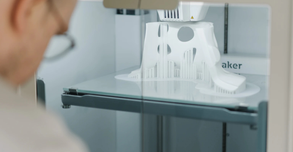
One of the most frustrating parts of most 3D printing processes is that it requires printing support structures. These become necessary the more complex your design is. Aside from using up more 3D printing material, these structures have to be removed during post-processing. This can often be a tedious process.
The bitter truth is that supports are practically unavoidable. However, support settings can be tweaked to make their removal a little bit easier. Here are some tips on setting your slicer for the painless removal of support structures.
How much support does your print need?
The best piece of advice for easy support removal is to print your model with as few supports as possible. The first thing you can attempt is to change the orientation of your model and check if it can be printed with fewer supports. It’s rare for this strategy to outright eliminate supports, but even a 10% to 20% reduction can be a huge help.
When reorienting your model, keep in mind that the basic function of support structures is to prevent overhanging features from collapsing. Thus, your goal is to reduce the number of overhanging features or maintain the overhang angles within a set threshold.
Overhang angle
The usual rule of thumb in 3D printing is that any overhanging feature that is angled more than 45 degrees from the vertical will need to be reinforced with a support structure. If you’re relying on your slicer’s automatic ‘Generate Supports’ command, then this will likely be the basis for the placement and number of supports.
However, some slicers allow you to play around with the overhang angle settings. Depending on your design and the filament you’re working with, you can try to set a higher overhang angle. There have been cases where a setting as high as 70 degrees still works. This should significantly reduce the number of supports that will be printed.
Placement
There are two options when it comes to support placement – you can choose to place them ‘Everywhere’ or only where they ‘touch the build plate.’
If you want to make support removal as easy as possible, then choosing to build them only on the build plate is the preferable option. This removes any support structures that would have to be built inside of a model.
The advice to print supports only on the build plate may not apply in all circumstances. Highly complex models may benefit from having internal supports. However, internal supports can be a bit tricky to remove. You will have to do a bit of experimentation to find which settings work best for your model.
Support pattern
The support pattern determines the internal structure of your supports. The options will likely be the same ones available in the infill pattern setting of your slicer. The usual recommendation is to avoid overly strong patterns such as grid or triangle unless absolutely necessary. Grid or triangle patterns are very stable but are also very hard to remove and can take a lot of printing time.
For easiest removal, the standard zigzag pattern would be the best option. You can also choose to strengthen this pattern by enabling the “connect zigzags” setting. Supports in a zig-zag pattern can be removed quickly because they pop off in just a single piece.
The next strongest option would be the lines pattern. This pattern provides just about the same level of stability as zigzags but does not come off quite as easily. The lines pattern is an excellent middle-ground option and works well in most cases.
For parts that have circular or close to circular shapes, the most optimal support pattern should be concentric. This pattern provides both good stability and ease of removal given that you use it under the right circumstances.
Infill line direction
As an auxiliary setting to the infill pattern, you can also set the angle of orientation of the infill. The default option has the pattern set diagonally by 45 degrees. This usually already works well to counteract the X-Y movement of the print head.
The orientation of the infill pattern is not a significant factor in ease of removal. Just make sure to remember the infill direction you used and peel off the supports layer by layer.
Support wall line count
You can choose to print a wall or outside perimeter on your support structures. This reinforces support structures but also makes them harder to remove and increases printing time. Adding a wall is not necessary unless you’re working with an exceptionally soft filament like PVA or TPU.
Support infill density
Just like the infill of your 3D print, the infill of the support structures also has an adjustable density. Coming up with an optimal value for support infill density is not straightforward and needs to take into consideration several factors.
Low-density supports (< 20% infill density) work well enough for overhanging features that are not very heavy and do not require many contact points. As expected, these are easy to remove but can also fall apart due to excessive vibration. High-density supports (> 20% infill density) are more rigid but also consume more material and printing time. They are also more difficult to remove. If you have a complex design or large overhanging features, high-density supports may be necessary.
If you’re unsure what setting to use, then starting with low values from 10% to 20% is considered a more effective and conservative approach. You can adjust accordingly if overhanging features fail with these settings.
Support brim
A support brim acts just like the brim for the main print – it is an extra layer of material printed around the base of the support structure to aid in bed adhesion. You can consider enabling this option if you’re printing with a material that is prone to warping or if the support structures do not have a lot of contact area with the build plate.
You can also choose to adjust the width of a support brim. A wider brim provides better reinforcement but is consequently harder to remove from the build plate. The brim width is not a factor in determining the difficulty of separating support structures from the rest of the print.
Z distance
The Z distance setting of your supports is probably the most important parameter in determining how easily they can be removed during post-processing. There are two terms under the Z-distance setting:
- The top distance is the distance between the top of the support and the bottom of the model. This is the more important setting of the two.
- The bottom distance is the distance between the bottom of the support and the top of the model. This only becomes essential if internal supports will be built into your model.
Increasing Z distance settings makes support removal easier as it leaves a larger gap between the model and the support structures. However, the lower number of contact points also means that the reinforcement provided by the supports is weaker.
The most common piece of advice is to set the support Z distance to be twice that of the layer height. This is a good starting point. Some adjustments may be necessary based on the complexity of your model and the filament you are working with.
X-Y distance
If your supports need to be built side-by-side with other vertical sections in your model, then you can adjust the X-Y distance to set a horizontal clearance. Reducing the X-Y distance will provide better support but also make these support structures more difficult to remove.
The X-Y distance is not as critical as the Z-distance setting when it comes to determining the strength of the support structures. It is considered good practice to set the X-Y distance two or three times higher than the Z-distance.
Support distance priority
In some cases, it may be physically impossible to satisfy your Z distance and XY distance settings simultaneously. It’s almost impossible to avoid such a situation given how geometrically complex most models for 3D printing are. The ‘support distance priority’ option reconciles this matter.
Under support distance priority, you only need to choose whether to prioritize the Z distance or the XY distance. The priority option will not adjust for the rest of the print – however, the other variable can increase or decrease to accommodate the priority values.
It is almost always better to prioritize the Z distance over XY distance. Slight adjustments in Z distance can compromise the quality of support of a print or make the support structures unexpectedly hard to remove.
Minimum support area
By default, all overhanging features will be reinforced with support structures. You can filter out some of these supports by setting a minimum footprint area that will have to be supported. This is a good strategy if you find that a huge number of very thin support structures appear in unwanted places. Be careful when setting too high values for the minimum support area as you may end up with features that fail due to a lack of support.
Join distance
The join distance setting will act as the maximum X-Y distance allowed between two adjacent support structures. If the structures are closer than this pre-set value, they will be merged into a single column. This setting helps strengthen support structures that are very thin but also makes them harder to remove.
Use towers
Towers are support structures that are wider at the base and taper off towards the top. They are ideal for supporting very small overhanging features. You can also adjust the angle at which the towers tape off so they can be wider or narrower to your liking. Since they have a very small contact area with the print, support towers are typically much easier to remove than regular supports.
Support interface
A support interface is a layer of material that sits on the roof of the support structure. This extra layer adds extra reinforcement to the print, strengthening the support without having to resort to very dense supports.
The support interface feature was designed for use with dissolvable support material. Having a continuous skin of material on top of supports was a great method for enhancing the surface quality of the main print.
However, some users have been able to use the support interface function to make any support easy to remove. If you set a large enough z distance gap and combine it with a support interface, supports can come off with hardly any effort. Take note that you can also make supports very hard to remove if you do this technique wrong – best to do a bit of practice with a smaller print.
Printing temperature
One setting that is often neglected when it comes to optimizing supports is printing temperature. Printing at higher temperatures promotes stronger material adhesion. When supports are printed too hot, they tend to bond too well with the rest of the print and become harder to remove.
Final thoughts
Support structures have always been a necessary evil in 3D printing. As difficult as they are to remove, they are usually needed for very complex designs.
The best strategy would be to reorient your model so that it will print with as few supports as possible. There are about a dozen parameters that you can play around with to make support removal easier – you just need to understand what each setting does.