
A Troubleshooting Guide to Common 3D Scanning Issues

3D scanning technology may seem magical to many as they transform real-world objects into digital assets. This technology has become very accessible nowadays, with some smart phones able to use apps that can do basic 3D scanning.
However, 3D scanning technology is not foolproof. There is proper technique involved in making sure that objects are scanned accurately and with no loss of details. There are also specific conditions that make 3D scanning more difficult. In this article, we will be going over the usual issues encountered in 3D scanning and how to resolve them.
How 3D scanning works
To better address problems encountered in 3D scanning, we must first understand how this technology works. The goal of 3D scanning is to generate a 3D model of a real-world object, either as a point cloud or as a series of tessellated surfaces. There are generally two ways that this is achieved by modern devices.
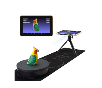
- Photogrammetry refers to the process of stitching together several images that overlap with each other and are taken at different angles. An algorithm identifies the pixels that are similar across the different images and uses these as anchor points for stitching.
The main advantage of photogrammetry is that it can be done with just a standard camera. Through this technique, it is now possible to do 3D scanning using just your smart phone with the appropriate app. There is still a lot of data processing involved in making the composite image in photogrammetry, so this is typically done using cloud-based servers.
There is some limitation in the accuracy and resolution of photogrammetry, especially if you’re just using a smart phone camera. It also needs to be done in an area with good lighting and the object must not have shadows or overly reflective surfaces. However, photogrammetry is considered a good entry-level 3D scanning technique.
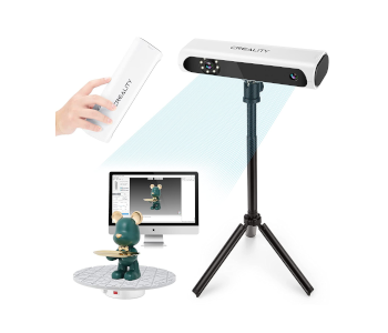
- Most professional 3D scanners use a light-based method. This involves emitting beams of light on the object being scanned and having them reflect on its surfaces. These beams are then received by a sensor. The time-of-flight (TOF) of the light particles is then interpreted to infer the object’s geometry.
Laser pulse scanning, LiDAR scanning, and blue light scanning are all considered different techniques under the light-based scanning category. These techniques use light at different frequencies and intensities. Light-based 3D scanning is generally considered to be more accurate and more appropriate for capturing very fine details. However, they can still run into difficulties when scanning less than ideal surfaces. Light-based 3D scanners are generally more expensive.
In the past, there were 3D scanning assemblies that used tactile sensors to make measurements of each part of an object. These are no longer commonly used today because they are difficult to use and expensive.
Light plays an important role in modern 3D scanning technologies, whether it is based on photogrammetry or a purely light-based method like LiDAR. As we shall see later on, the interaction of light with the object being scanned is also the reason for the challenges of 3D scanning.
Common issues encountered in 3D scanning
3D scanning of clear, glossy, or black surfaces
The most common problem in 3D scanning has to do with dealing with objects that have clear, glossy, or black surfaces. Recall that both photogrammetry and light-based methods rely on the phenomenon of light bouncing off the surfaces of the object being scanned. Problems come up when the surface of the objects either reflects too much light, does not reflect light at all, or absorbs all of the light.
Seeing as this is a very common issue, there are actually several ways to go about addressing it. Some laser or structured light 3D scanners offer the option to adjust the intensity of the light source to reduce the errors when scanning these types of surfaces. This can be done manually in most models. There are also models that can perform real-time automatic adjustment of the light source and this often yields the best results.
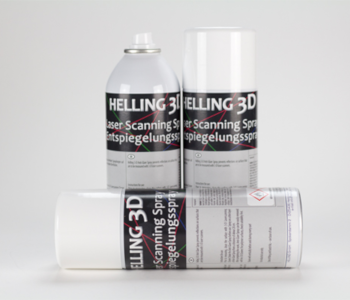
If exposure adjustment is not an option, another common solution is to treat the surface of the object with a 3D scanning spray. This spray gives the surface of the object an opaque and textured appearance, making it more suitable for scanning. The AESUB 3D scanning spray is one of the more popular products in this market. The material itself disappears after a few minutes and does not cause any damage, even for electronics.
3D scanning of thin objects
All 3D scanning methods have limitations in terms of the level of detail that they can capture. This can be problematic when the object you’re scanning has very small details. What is even more problematic is if your object has parts that too thin to be detected by the scanner.
In some cases, the thin edges can be detected but are not scanned properly. This is mostly because the reflection of light tends to become less predictable on very thin edges. This can result in parts that are distorted or have lots of holes in them.
When this happens, you can try to adjust the 3D scanning parameters, such as the distance of the scanner from the object, or do repeat scans. However, there are cases when errors are unavoidable. In such a situation, the best solution is to reconstruct any missing features using 3D modeling software. This issue emphasizes the importance of knowing basic 3D modeling should you get into 3D scanning.
3D scanning of objects with holes and cavities
Another limitation of 3D scanning is that it only captures features that can be reached by light. This can be problematic if you’re trying to scan an object that has lots of internal details, such as cavities. Holes on the surface of the object can also be problematic and may be difficult to interpret for the 3D scanning algorithm.
Unfortunately, this is a natural limitation of the technology and can only be solved by using technology that is more appropriate for the situation. Computed tomography (CT) devices that use X-rays can be good alternatives for 3D scanning of objects with an internal cavity. These are less common and may be more difficult to access.
Misalignment while 3D scanning
The algorithm of 3D scanners automatically designates physical markers in the object as references for stitching together overlapping images. This is done usually based on the geometry or color of the markers. However, this is not a perfect process. When physical markers are not aligned properly, the generated model tends to have features that are misaligned.
Misalignment typically happens when there are not enough physical markers between two images being stitched together to allow for perfect alignment. This can be due to the object rotating too quickly or because of any unusual geometry in the object. Either way, this is a temporary problem and is easily resolved.
The best thing to do in this situation is to reposition the object in a manner that allows the 3D scanner to see previously acquired markers. Just doing this is typically enough to solve alignment problems. You can also choose to individually delete misaligned layers and scan those parts again. Rescanning slowly and with better lighting may yield better results.
Missing points while 3D scanning
It’s actually rare to get an error-free model of any object with just a single pass of 3D scanning. You will likely end up with holes, missing sections, external artifacts, and misaligned layers. These are problems that can be solved by doing multiple scanning passes. If they still persist, then there might be something wrong with the setup.
Some 3D scanning software may show a prompt that says that there are too few points being generated from the scan. On the model, this will manifest as missing sections, perhaps widely distributed across the model’s surface. When errors are all over the model and not isolated on just a single part, it could be a sign that the scanner is too far from the object.
Make sure to keep the scanner within the distance prescribed by the manufacturer. It’s also a good idea to keep the scanner pointing to an area that has already been scanned to help in re-establishing physical markers. Some scanners have a depth camera that displays how much of the object it can see at any given point.
Knowing that these errors can come up in 3D scanning means that you should be better prepared when they come up. A can of 3D scanning spray should help in most cases, as does a basic knowledge of 3D modeling and mesh editing.
Final thoughts
Whether you’re doing it with a smart phone or with a commercial 3D scanner, making 3D models based on actual, physical objects is a lot of fun. There is also plenty of commercial and industrial opportunities for this technology, especially if you know how it works and how to iron out the inevitable kinks. 3D scanning isn’t magic – it’s just new technology. As with any technology, things can go wrong sometimes.